One + C Cell Manual
Product Support and Customer Service
For Further support visit our Contact Page
Safety
Think and act in a safe manner. Always disconnect power and use a lockout before you work on the E-coat system, or any of the related subsystems. Observe any confined space conditions. Use the appropriate safety equipment and clothing for the task. Please carefully read all the instructions listed below to familiarize yourself with the project before attempting to perform any of the work.
Description and Function
This manual provides general operating and maintenance instructions for the One + C-Cells that share the following characteristics:
Electrodes composed of 316L stainless steel (or other optional materials made from more inert materials) and rolled membrane (PTAR).
A unitary-construction semi-circular One + C- Cell, designed to meet the needs of automotive E-coat paint systems. This cost-effective design also includes an improved anolyte flow pattern providing for longer Anode Cell life. This design eliminates flange nuts and bolts which are proven to be typical leak points. It has more anode and membrane surface area than competitive C -Cells, improved anolyte flow pattern, and no leaks. The One+ C Cell is a superior design for automotive E-coat paint systems.
The One + C-Cell is a flushable Anode Cell used in an electrocoating paint system with most types of paint. It serves as the opposing electrode and simultaneously removes solubilizer, or neutralizer (usually a common organic acid) from the paint to maintain chemical balance.
System Requirements
If UFS Corporation provides the Cell Circulation System (CCS), a separate manual will be furnished. The following are some general guidelines for system design:
A. See the Appendix titled “Recommended Anolyte Pump Flow Rate,” for the recommended circulation pump specification. The foregoing criteria assumes that the Cell Circulation tank and pump are a maximum of 3 m (10 Ft.) below the tops of the Anode Cells. Increase the friction head equipment, if necessary. The CCS should include a suitable rotameter and pressure gauge to confirm that these criteria are being met.
NOTE: As paint can get into the anolyte and cause seal failure in a horizontal pump, we recommend using vertical pumps or magnetic drive horizontal pumps.
B. See Appendix titled “Recommended Anolyte Tank Volume,” to determine the Cell Circulation tank capacity.
C. A 1/2” valve with a flow indicator is recommended to regulate the anolyte supply to each Anode Cell. A valve of this size gives reasonable control in the recommended flow rate range.
D. The anolyte supply manifold branch should be 102 mm (4”) PVC Pipe (Schedule 80) minimum, sized not to exceed a velocity of 0.25-0.5 m/sec. (3-5 ft/sec.). A siphon breaker at the termination point of each leg will prevent siphoning of the Anode Cells after anolyte pump shutdown. This will prevent excessive anolyte tank draw-down when the anolyte pump is restarted. Main trunk (at anolyte pump discharge) should be one pipe size larger.
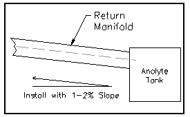
E. The anolyte return manifold branch should be at least 152 mm (6”) PVC pipe (Schedule 40), minimum and sloped toward the anolyte tank at a pitch of not less than 1-2% slope (1/4” per foot). Size so that it is NO more than 3/4 full at the lowest point. To prevent vapor lock, it should be vented at the high end of each termination leg. Main trunk (at anolyte pump return) should be one pipe size larger.
F. Cable connectors to individual Anode Cells should be designed for fifteen (15) amps of current flow per meter (5 amps/foot) of effective Anode Cell length. Only stainless steel nuts, bolts, and compression washers should be used. UFS supplies a set with each Anode so that high resistance problems due to corrosion are avoided.
G. It is desirable to have an amp-hour meter on the rectifier feed to the One + C- Cells and ammeters on the entrance zone Anode Cells. Information from these meters is often very helpful in diagnosing Anode Cell performance problems. UFS has a range of products that can assist current monitoring needs to maximize optimal results from your e-coat tank.
Installation
Step 1
Anolyte Supply Manifold (If supplied by UFS Corporation)
The anolyte supply manifold is normally a 102 mm (4”) diameter Schedule 80 PVC pipe. Couplings and caps are supplied to join the sections; however, and the customer must supply the PVC primer ( purple schedule 80 tape) and cement (heavy body Schedule 80 tape). Support PVC Manifolds every 1.5 m (5’).
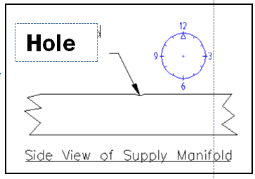
The spacing of the anolyte valves on the anolyte supply manifold is usually indicative of the actual spacing of the One +C- Cells in the e-coat tank. Each section of the manifold is labeled on a particular end with a sequence number and either a left or right notion. For example, if three sections of pipe are required to run the length of the tank, six pieces would be supplied (e.g. three pieces per side). The “A” and “B” notion differentiates the two sides and are not necessarily specific. The match marks make sure the individual sections of pipe have the proper alignment. Insure that the drilled holes in the pipe are in the 12 o’clock position.
Grasp the sections labeled “A” or “B”, Number 1 on the end with the marking. The first threaded hole from the end with the marking should be located at the proper distance (see reference drawing attached or note on pipe) back from inside of the e-coat tank. This distance is generally written on Section 1. Grasp the section labeled “A” or “B”, Number 2 on the end that is marked and attach that to the back of the first section. The end with the marking should always point toward the front of the E-Coat tank. Join the two sections of the manifold using the couplings supplied. Continue until all the sections are installed on both sides of the tank.

Siphon Breaker Kit
When the circulation pump is turned off, it is possible that the anolyte can be siphoned from the Anode Cells, if a siphon breaker is not used. If siphoning has occurred, the operator, upon restarting the circulation pump, may get a low level alarm in the anolyte tank, since the pump has to first fill all the One + C- Cells before any fluid is returned to the tank.
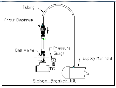
Install the check valve with arrow pointed down so that it is closed when the pump is turned on. (See diagram) When the pump is turned off, the check valve opens, air enters the supply manifold from the connection to the return manifold and breaks the siphon.
A siphon breaker should be installed at the termination of each supply manifold. Also included is a pressure gauge which can be used when trouble-shooting. The bottom of the check valves must be located at least 150-300 mm (6” to 12”) above the top of the Anode Cell. See your General Arrangement Drawing.
Step 2
Anolyte Return Manifold (If supplied by UFS Corporation)
The anolyte return manifold, usually 152 mm (6”) is laid out and assembled the same as the anolyte supply manifold. Since this is a gravity return system, the flow of the return header should be toward the CCS tank at about 2% slope (1/4” per foot). The high end of the return manifold must be vented at least 150 mm (6”) above the top of the Anode Cell for proper operation to avoid vapor lock. Support the PVC Manifold every 1.5m (4’ to 5’).
Grasp sections “A” or “B”, Number 1 on the end with the marking. Place towards the anolyte tank. The first drilled hole from the end with the marking should be located at the proper distance (Ref: General Arrangement or note on the pipe) back from the inside front edge of the E-Coat tank. Grasp section “A” or “B”, Number 2 on the end that is marked and attach to the back of the first section. The end with the marking should always point toward the entrance of the tank. Join the two sections of the manifold using the couplings supplied. Continue until all sections have been installed on both sides of the tank.
Note: Proper care should be taken when installing the supply and return manifolds. The centers of the connection holes in each manifold should line up exactly with the centers of the Anode Cells. Also, PVC DWV long sweep elbows and tees should be used on the return manifold to lessen the chance of restricting the gravity flow.
Step 3
UNPACKING THE One+ C-CELL CRATE
Remove the lid and any hold-down blocks along with any exposed nails, staples etc. that might puncture the Shells. Do not remove the cardboard or plastic packing at this time . It will protect the Shell as it is taken from the crate into the E-Coat system. Remove the cardboard and plastic packing immediately before you install the Anode Cell in the tank. TAKE CARE NOT TO PUNCTURE OR DAMAGE THE One + C-Cells. Significant cuts or punctures generally cannot be repaired, which renders the entire C-Cell unusable. The One + C-Cells should always be supported at the bottom and top to avoid damage to the membrane. Carefully inspect each One + C-Cell for possible defects and report any defects immediately to UFS Corporation. Cuts or punctures due to improper handling are the responsibility of the owner/installer. Anode Cells with manufacturing defects will be repaired/replaced free of charge by UFS Corporation, upon return of the defective item. (Note: Items that are sent back to UFS for inspection must be sent prepaid and require prior authorization.)
NOTE: One+ C-Cells are heavy and must be carried by at least two persons, following your company’s lifting protocol.
NOTE: Initial installation of the ME Cells should be done immediately before the tank is filled with paint so the Anode Cells can be checked for leaks with either DI or RO water. The less time the Anode Cells are in the tank before the paint fill, the less likely they will be damaged. If paint tank is full the cells must be filled with DI or RO water before they are installed.
Step 4
Mechanical Support
Mount the One + C-Cell to the Square bar found on rim of tank. Adjust universal bracket accordingly so that the One + C-Cell hangs level. See Installation Reference #993172.
Step 5
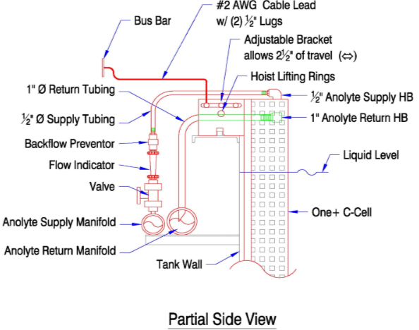
Electrical Connections
Electrical supply involves the connection of power from the local bus bar to each One + C- Cell with an appropriate cable lead and the supplied stainless steel hardware set. The cable lead should be sized by the system designer, with the expected current draw of each One + C-Cell, as specified by the paint supplier, taken into account.
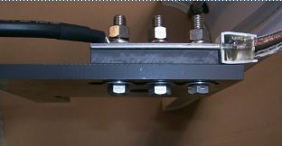
Connect the electrical cable to the inside part of the tab with the 1/2” SS nut, bolt, and lock washer set provided. See Installation Reference #993172.
Diodes are normally recommended on the lower voltage zone of a multiple voltage zone E-Coat system to avoid reverse power conditions. Contact UFSc Technical Department for more information on this matter.
Step 6
Manifold Supply Hook Up
Anolyte solution supply is conveyed to each One + C- Cell from the supply manifold via 12.7 mm (1/2”) I.D. flexible PVC tubing attached to the C-Cell. The flow of anolyte to each One + C-Cell is usually controlled by a 1/2” PVC valve with flow indicator. Anolyte solution overflows from the anolyte overflow nozzle, The wall thickness of the PVC return tubing should be about 2 mm (3/32”) to avoid kinks.
Supply Tubing Preparation and Insertion
Cut the anolyte supply tubing, attached to the One + C-Cell, to the appropriate length (e.g., leave about 300 mm (12”) of slack). Connect the tubing to the corresponding flow indicator on the supply manifold.
Step 7
Return Tubing Preparation and Insertion
Cut an end of the return tubing at a 45 degree angle for insertion into the return manifold. From that cut, allow 25mm (1”) insertion length into the return manifold, then measure a length of tubing so it will not kink when installed. Cut the other end off at 90 degrees and lubricate the inside with a little water (Do not use any lubricant containing silicone.) Connect this end of the tubing to the One + C- Cell overflow nozzle. Push the other end no more than 25 mm (1”) into the corresponding hole in the return manifold.
Step 9
Leak Testing Before Start-up (All One + C-Cells have been leak checked before shipment)
After all One + C-Cells are installed and the anolyte piping has been flushed, turn on the Cell Circulation System and adjust the flow rate to each Anode Cell for approximately 8.0 lpm/sm (2.0 gpm/sf) of Anode area no less than 1.5 lpm/cell (1/3 gpm). Do not exceed 7 psi in inlet manifold. Check each One + C- Cell for leaks. The One + C-Cells are warranted against leakage due to materials and workmanship (see warranty). The Membrane does have a finite water permeability, and it is normal for it to become wet and “sweat’ after several minutes. Report any defective Membrane Shells, or shells that have excessive Membrane permeability, immediately to UFS Corporation. UFS Corporation will tolerate 500ml/hr for PTAR Membrane.
Operation
The essentials of normal operating procedures are:
- Establish and maintain proper anolyte flow and conductivity to each One + C-Cell.
- Periodically inspect the anolyte overflow tubing for signs of paint leakage into the anolyte
- Monitor the total current draw and voltage
- Check the color of the anolyte each shift (See appendix page 26)
During the first several weeks of operation, close attention should be paid to the color of anolyte. Occasionally 316 SS Anodes will be attacked by some contamination in the paint bath of the anolyte circuit. If this is occurring, Anodes will become pitted and the anolyte will be discolored (brown or black, rather than a normal clear, pale-yellow color). If these conditions are observed, it is important that prompt action be taken. Contact UFS for assistance. UFS strongly recommends the use of any anti-corrosive additive that your E-Coat paint supplier might suggest.
Anolyte Fluid Conductivity
Conductivity of the anolyte should be maintained in accordance with the paint manufacturer’s recommendations. Anolyte conductivity is a qualitative, not a quantitative, indication of acid concentration. During the painting process, the acid concentration and the conductivity of the anolyte will continuously increase. The conductivity is controlled by purging the anolyte from the Cell Circulation System and replacing it with fresh deionized water. The anolyte purge can be accomplished manually or automatically with a conductivity controller and electric ball valve. On smaller systems, it can be done on a batch basis.
Anolyte Fluid Flow
It is very important that proper anolyte flow be maintained to each individual One + C-Cell. C- Cells should be individually inspected every day to confirm that the flow is adequate.
It is possible to provide anolyte flow indicators with each One + C-Cell. With a little experience, however, an operator can establish suitable flow rates by eye. The exact flow rate is not critical. However, in general (so long as the C- Cell does not overflow) the higher the flow rate, the better. With normal Cell Circulation System pressure a 1/2” ball valve will usually produce a suitable anolyte flow near the “3/4 open position.” It is difficult to tell if the anoolyte is flowing by looking at the anolyte supply tubing, but the flow can always be confirmed by inspecting the anoolyte overflow tubing.
Electric Current Draw
Workforce safety is always a foremost concern. Directly measuring current is very risky and requires a significant amount of prior planning and safety consciousness. Baselines are necessary for lowest lifetime cost operation. It is critical for an E-Coat system’s successful operation to establish a baseline for each important parameter. The minimum baseline for an individual One + C-Cell relates to the smallest load and largest load. With each, the peak and valley (or minimum for a hoist system) should be established. (Each C-Cell will have four baselines recorded.)
To measure One + C-Cell performance, it is important to know your wiring infrastructure, specifically how your C-Cells are connected to the electrical distribution bus. If each C-Cell has an individual cable lead, it is possible to measure its current flow. If C-Cells are connected by a “daisy chain,” you will need to upgrade wiring by installing a single cable lead for each C-cell before you implement most current measuring methods.
Valuable information can be gained by connecting measuring equipment. UFSc has developed a New Generation Anode Monitor™ System that allows tank E-Coat system personnel to monitor individual One + C-Cells. By displaying information on peak current as well as total accumulated Amp hours.
Installing an Anode Monitor System will provide visualization for electric flow. Every E-Coat system has some amount of fault tolerance so when equipment begins to weaken it may not be apparent if the only guide to assessing performance is E-Coat film thickness. Anode monitoring provides an early warning system that will show if equipment in the E-Coat system has been compromised. Anode monitoring will assist in producing a good estimate of when a danger point may be reached. Equipment budgets can then be prepared in a timely manner to avoid downtime.
The amount of current delivered by each One +C- Cell determines the total amount of E-Coat film deposited on the ware. Individual C- Cells should draw no more than 55 amps/sm (5 amps/SF). If the entrance zone One + C-Cells draw more than this amount, these C- Cells should be moved closer together to reduce the current draw of the first C- Cell.
Regular logging of system data is essential to diagnose operating problems and plan the orderly replacement of Anode Cells. The following key data should be recorded at least once a day:
- Anolyte Conductivity
- Paint Bath pH and conductivity
- Total Anolyte Flow (gpm)
- Rectifier Voltage (each zone)
- Rectifier Amperage (each zone)
- Anolyte Color
This data should be taken at the same time each day, with the same work load in the paint bath. Optional data, useful for more detailed analysis, include :
- Amperage of individual C- Cells .
- Acid additions to the bath (gal/wk)
- Amps-hours of operation (amp-hr/wk)
MAINTENANCE
The routine maintenance required for the One + C- Cell is minimal. This section will address the maintenance procedures.
C-Cell Removal
To remove the Anode Cell for maintenance, inspection, replacement or long-term storage, do the following: MAKE SURE THE POWER IS TURNED OFF AND LOCKED AT THE MAIN PANEL! Never attempt to remove work on a “live” Anode Cell.
- Turn off the anolyte supply valve and remove the anolyte supply and return tubing from the valve.
- Disconnect the cable lead from the One + C-Cell. .
- If removing One + C-Cell from an empty e-coat tank the anolyte must be siphoned out. Do not let it siphon if e-coat tank is full.
- Use a hoist to slowly lift C-Cell out of tank. While C-Cell is being lifted make sure it is thoroughly rinsed with either DI or RO water. DO NOT ALLOW THE MEMBRANE TO DRY OUT while maintenance or inspection is performed.
LONG TERM STORAGE
As the e-coat tank level is lowered, spray the outside of the One + C-Cells with a D.I. water hose to rinse off paint solids. Remove the C-Cell and immediately store in a long poly sleeve (measuring 20” wide when flat and 6 mil. thick) and completely seal both ends to preserve moisture. Do not let the C-Cell dry out. Store C-Cells in the vertical position in order to protect them from being crushed by a heavy object.
REINSTALLATION OF THE CELLS
Reverse the sequence for reinstallation. However, it is important to note that the One + C-Cell will be buoyant and difficult to submerge if it is not filled with D.I. water. Remember to lower the One + C-Cell slowly into the e-coat tank.
ANODE INSPECTION AND CELL ROTATION
One + C-Cells have a limited life, and it is normal for them to deteriorate over a period of time. The Anode itself erodes naturally as part of the electrochemical process. The ion-selective membrane also deteriorates. It will slowly lose its acid removal capability, and its electrical resistance will increase. The rates of deterioration of the Membrane and Anode are functions of current density (amps/sf), paint chemistry, and other operating conditions such as anolyte chemistry and flow rate.
Under normal conditions and proper operating procedures, the Anode Cell will last at least two to four years before it has deteriorated to the point that it must be replaced. With a well operated and maintained system (proper anolyte flow rate and paint chemistry, etc.), the One + C- Cell life normally becomes a function of current density and operating time only. It is normal for One + C-Cells near the entrance zone of a mono-rail, conveyor-type electrocoat tank to deteriorate more rapidly than One + C-Cells near the exit end.
UFS Corporation recommends annual inspection of One + C-Cells, and to move less-worn Anode Cells forward. Entrance One + C-Cells that show signs of significant anode wear, or that have declined significantly in current draw, should be replaced.
SPARE PARTS AND ACCESSORIES
Contact UFS
WARRANTY
We warrant all equipment manufactured by UFS to be free from defects in material and manufacture at the time of shipment for a period of one (1) year from the date of shipment. We will furnish without charge, but not install, replacements for such parts as we find to have been defective.
This warranty shall not apply to any equipment which has been subjected to misuse, neglect or accident, or has been altered or tampered with, or if corrective work has been done thereon without our specific written consent. No allowances will be made for such corrective work done without such consent. Improper maintenance, deterioration by chemical action, and wear, do not constitute defects.
Equipment manufactured by others, and included in our offering, is not warranted in any way by us but carries only the manufacturer’s warranty, if any. All anodes (and or cathodes), of any material, are not warranted by us in any way since they by nature are sacrificial and will erode or corrode away with time.
All warranty claims must be submitted within ten (10) days of discovery of defects or shall be deemed waived. All parts returned for inspection must be sent prepaid. No representative of our company has any authority to waive, alter, vary or add to the terms hereof without prior approval in writing. The foregoing is in lieu of all other warranties (including that of merchantability), whether express or implied.
LIABILITY
It is expressly understood that our liability, including that for breach of contract, negligence, strict liability in term, or otherwise for our products is limited to the furnishing of such replacement parts, and that UFS will not be liable for any expense, injury, loss or damage, whether direct or consequential, including but not limited to loss of profits, production, increased cost of operation, or spoilage of material, arising in connection with the sale or use of, or inability to use, our equipment or products for any purpose, except as herein provided.
Appendix
One+ C-Cell Ammeter Log

One+ C-Cell Maintenance Log

Service Reference - Anolyte System Troubleshooting for One+ C-Cell
Service Reference - Anolyte System Troubleshooting for One+ C-Cell
Technical Reference - Membrane Electrode Glossary of Terms
Technical Reference - Membrane Electrode Glossary of Terms
Service Reference - Anolyte Color Evaluation
Service Reference - Anolyte Color Evaluation
Installation Reference - One+ C Cell
Installation Reference - One+ C Cell BULLETIN 994120