One+ C Cell
Product Support and Customer Service
For Further support visit our Contact Page
Safety
Think and act in a safe manner. Always disconnect power and use a lockout before you work on the E-coat system, or any of the related subsystems. Observe any confined space conditions. Use the appropriate safety equipment and clothing for the task. Please carefully read all the instructions listed below to familiarize yourself with the project before attempting to perform any of the work.
Required Materials
- Hoist / Lifting Materials
- Electrical Hardware for Bus Bar Connection
Required Tools
- Scissors
- Crescent Wrench x 2
General
Initial installation of the One+ C Cell should be done immediately before the tank is filled with paint so the One+ C Cell can be checked for leaks. The less time the ME Cells are in the tank before the paint fill, the less likely they will be damaged.
Step 1
Unpack the One+ C Cell carefully! First remove any exposed nails or screws from the shipping container which may cause damage.
Step 2
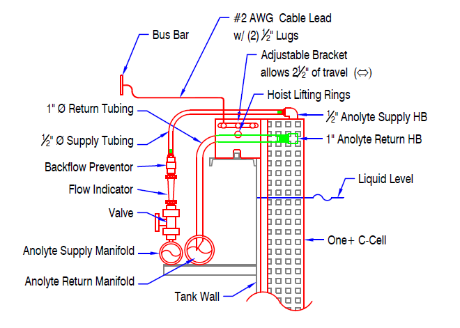
If using a hoist to place One+ C Cell into tank attach hoist to the hoist lifting rings (see insert). Mount the One+ C Cell to the rim of the tank using the universal mounting bracket (always use 2 people to carry). If the ED tank is full of paint, or partially full, fill the One+ with D.I. water first to avoid damaging the One+ as it is placed under the liquid level. Do a leak check for 30 mins.
Step 3
Connect one end of the electrical cable to the Stainlees Steel portion of the hanger that is attached to the Universal Mounting Bracket with 1/2” SS nut, bolt and lock washer set provided. Attach the other end of the electrical cable to the bus bar (hardware not included).
Step 4
Attach the 1/2” anolyte supply tubing (provided) to the PVC hose barb that is located above the return (SS coupling with hose barb). Cut the tubing to the appropriate length, leaving some slack. Connect the tubing to the corresponding hose barb on the flow meter assembly located on the supply manifold.
Step 5
Cut a 45° angle on one end of the 1” anolyte return tubing. This end will be inserted into the return manifold (Allow for 1” of insertion into the return manifold hole). Make sure the length of the tubing has some slack so the tubing will not kink when installed. Cut the other end of the tubing and connect to the One+ C Cell overflow nozzle (stainless steel coupling with hose barb).
Step 6
After all the One+ C Cells are installed and anolyte piping has been flushed, turn on the Anolyte Circulation System and adjust the flow rate to each ME Cell for approximately 7.6 - 11.4 lpm (2-3 gpm) per each One+ C Cell. Check each One+ C Cell for leaks. The Membrane Shells are warranted against leakage due to materials and workmanship. The membrane does have finite water permeability, and it is normal for it to become wet and “sweat” after several minutes. Let it sit for one hour; and if still leaking more than 350 ml/hr, take out of tank and inspect for damage. Immediately report to UFSc any defective ME Cells that you feel may have excessive membrane permeability.
BULLETIN 993171