Sensor, Current, 100A, 100mV, LB - 295025
Product Support and Customer Service
For Further support visit our Contact Page
Required Materials
- Mounting Hardware
Required Tools
- Crimper
- 7/16" Socket
Procedure
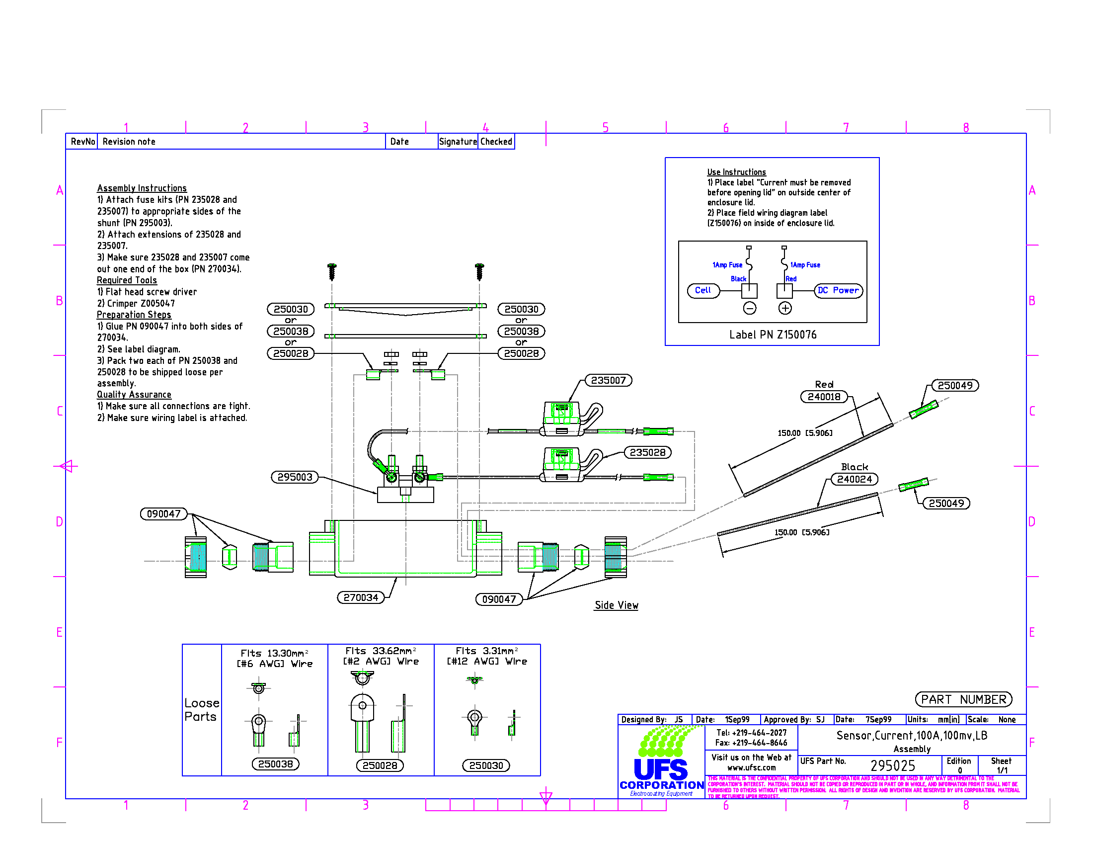
Think and act in a safe manner. Always disconnect power and use a lockout before you work on the E-Coat System or any of the related subsystems. Observe any confined space conditions. Use the appropriate safety equipment and clothing for the task. UFSc recommends that each of the Shunt Transducer leads be fused with a quick-blow 1/3 to 1 amp fuse. (Red and Black fuse kits with connectors and fuses come assembled with PN 295025.)
This Shunt is actually a high precision resistor used to measure current. For a DC Circuit, Volts = Current (Amps) x Resistance (Ohms). The measurement provided by the Shunt is a small DC voltage, generally less than 100 milliVolts. Since the resistance of the Shunt is known, then the current flowing through the Shunt causes a milliVolt drop (measured across the transducer).
The transducer leads from each Shunt are connected to a digital DC volt meter that is designed to convert the milliVolt drop across the Shunt. Each Shunt has a maximum current capacity of 100 amps, which is stamped on the Shunt. If the Shunt experiences a higher current, then it is likely the Shunt will fail (open), as it acts similar to a fuse.
Part Number 295025, Current Sensor assembly, is sent with everything but the #2 - #8 AWG wire. You have the option of using different gauge insulated wire depending on specific electrical code or industry standard.
Installation:
1. Select location to mount Shunt assembly PN 295025. Mount as required.
2. See the figure above.
3. Determine what gauge size of insulated wire that will be used from #2 or #6 AWG as two of each size crimp connector is supplied ( 250038 for #6, 250028 for #2).
4. Attach 6.4mm (1/4”) round lug to DC Power (line) from rectifier bus bar. Remove the ¼” brass nuts and brass washer from 295003 on the leg that the Red (same side as 235007) wire is attached.
5. Place round lug (supplied) over post and secure with brass washer and nut.
6. Repeat step 3 for the cable (same side as 235028) going to the Cell (load side).
7. Attach the insulated wire from the side of the Shunt that has the Black 235028 fuse from Step #5 to the TECTRON Membrane Electrode Cell.
8. Secure the LB enclosure box lid and gasket to enclosure box.
9. Ensure that all electrical connections are tight and minimize the amount of exposed wire and/or connector lugs.
For more information see the original manual that came with the equipment or call UFS.
BULLETIN 993151