TruPoint Manual
Contents
- 1 Product Support and Customer Service
- 2 Unboxing
- 3 Introduction
- 4 Product Features
- 5 Precautions
- 6 Keys to Success
- 7 Operation
- 8 Trouble-Shooting
- 8.1 Arming the Device
- 8.2 Board pulled out when USB connected was removed
- 8.3 Lost the O-Ring
- 8.4 Reset
- 8.5 Spare Parts List
- 8.6 Advanced Features
- 8.7 Changing Label
- 8.8 Set-up
- 8.9 Default
- 8.10 Custom
- 8.11 Calibration
- 8.12 Voltage
- 8.13 Temperature
- 8.14 Correlation Studies with Film Thickness
- 8.15 Aluminum Panels,Use Optional Auxiliary Magnet
- 8.16 Product Drawing
Product Support and Customer Service
For Further support visit our Contact Page
Unboxing
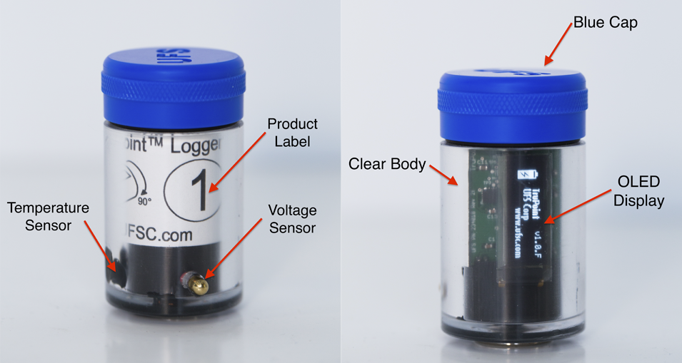
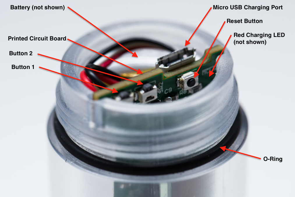
Product Features
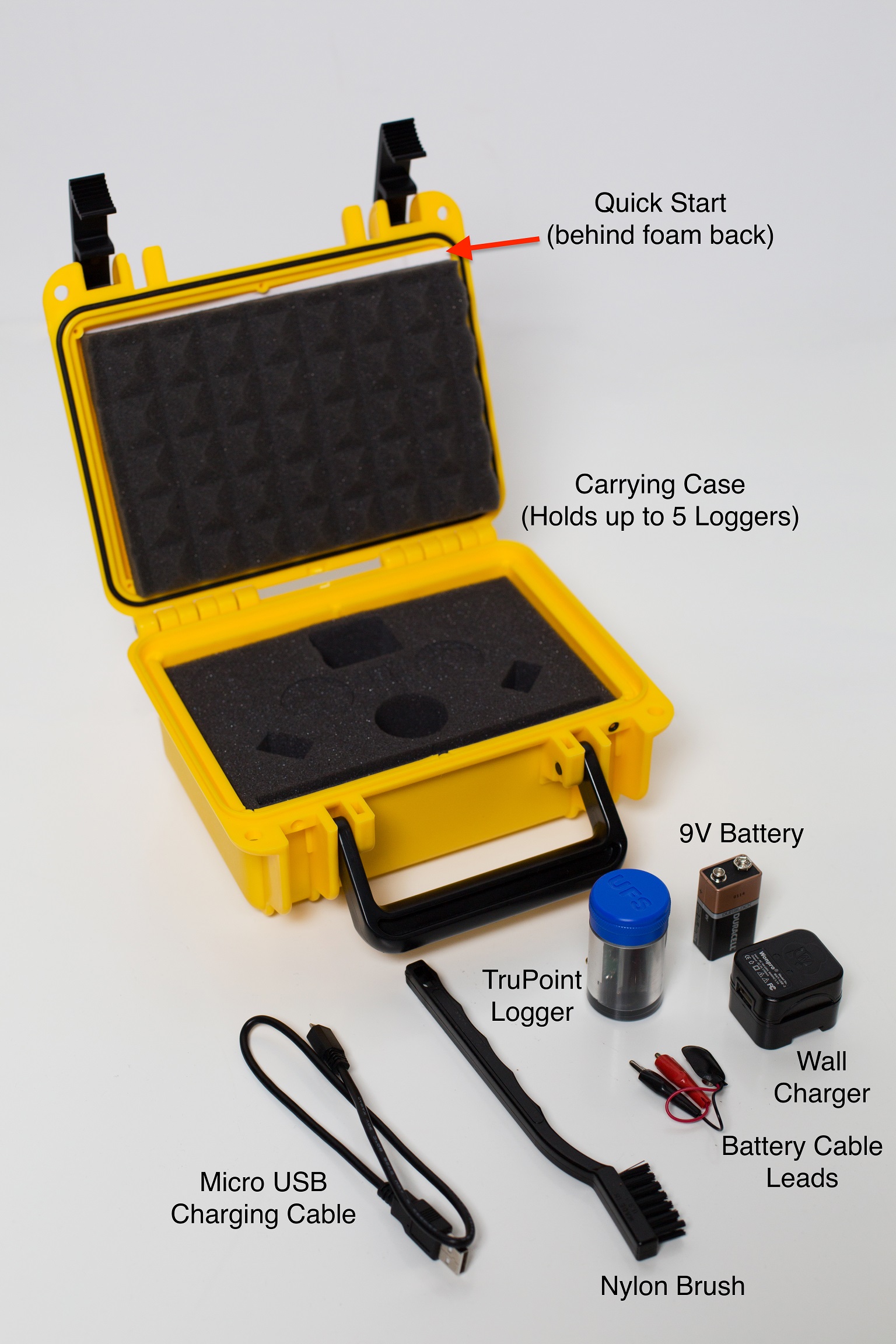
Not shown - TSA & Customs form for checked and carry on luggage as well as (3) Spare O-Rings.
Precautions
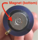
The Logger is meant to be submerged for several minutes at a time to an approximate depth of 1 m (3 ft) for a short duration in the E-coat bath. Because the case is made from PTEG, the upper temperature limit is 65 C (150 F), therefore the unit must be removed prior to the curing oven stage of the E-coat paint process. Since there are so many different chemicals used in the pre-treatment, it’s not possible to test them all for harmful effects on the plastic PTEG case. Phosphoric acid is an aggressive agent especially with plastics. If there is a line break and the logger is stuck in the acid for a long time, detrimental effects can occur. For this reason, strong acids will reduce the service life of the plastic case. Confirm that the 100% petroleum jelly used to help seal O-ring under blue cap is approved for use with your E-coat paint supplier. If not, ask them for an approved substitute you can use. Solvents (Acetone, MEK, Butyl Cellosolve, etc) should NOT be used to clean any of the plastic, or epoxy/glue parts of the unit. UFS recommends using ONLY isopropyl alcohol to clean the metal and plastic parts after a run. Use ONLY the included nylon bristle brush on the round magnet face on the bottom of the Module and on the brass voltage sensor tips. Do not use the nylon bristle brush on any plastic parts or on the glue that holds the magnets on the back of the Module. This will scratch the plastic case and damage the glue joints. The magnet on bottom of module will create an E-coat paint defect ( a small-uncoated spot 20mm in diameter), that has to be repaired post E-coat. The magnet should also be kept at least ½ m (20 in) away from magnetic records like those found on credit cards. For persons with medical implants, keep the magnet a full meter (40 in) away from any devices. Because of the LiPo battery - do not place in checked Luggage. You must carry on the device.
Keys to Success
If the Logger has not been used in the last 5 days, the battery must be fully charged before use. Use the supplied USB Wall Charger. Make sure the voltage sensor tip & magnet surface has been cleaned. If in doubt, use the brush to scrub the brass tip and face of magnet. Document locations of the sensors with a camera. Insure the magnet on the back of the Module are on the ware (or carrier – cathode) and the auxiliary ground clamp is attached to the ware too (redundancy). Make sure the blue top cap is fastened. Turn auto voltage controllers OFF (i.e. manual operation) and set the voltage set point(s) manually. Remove the Logger from the ware before the ovens and clean with IPA
Operation
Charge Battery
Charge the battery first via Mini USB cable & USB wall charger. Remove the Blue cap. Grasp the Micro USB connection and insert it as shown in the photo below.
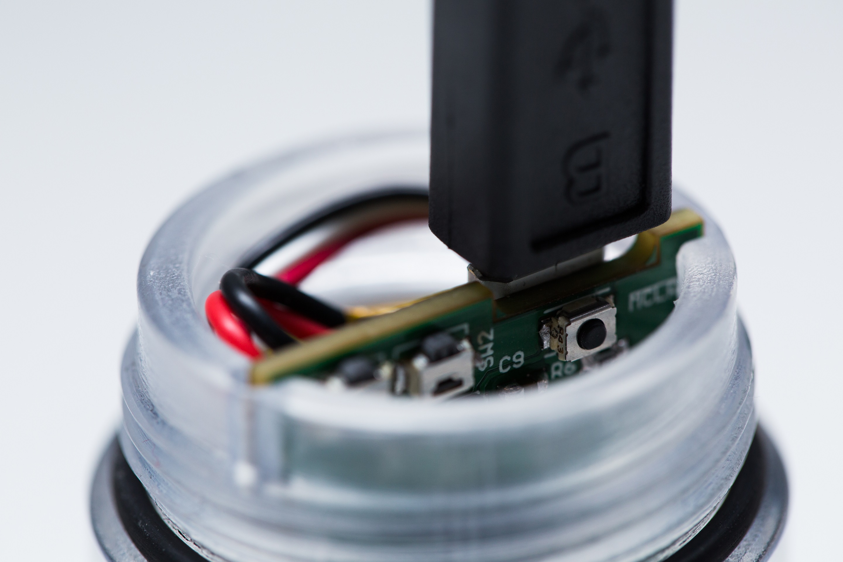
The LED will illuminate red indicating the LiPO battery is being charged. After the Red LED goes off, the battery is fully charged. Disconnect the USB cable from the wall charger. Hold the Logger with your thumb over the lip of the body and the printed circult board. Then gently remove the USB connector.

The maximum battery charge rate is controlled by a onboard chip and is limited to no more than 0.5 amps. Thus the minimum time to charge a fully drained battery is almost 2 hours.
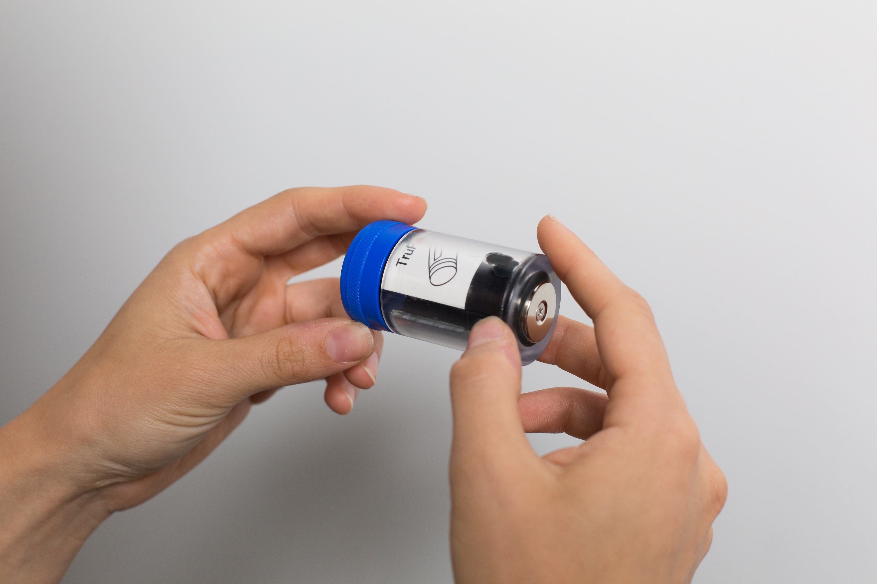
Wake up the Logger
The logger has an accelerometer chip that senses movement in the X, Y, and Z planes. This motion sensing is used to determine if you want to wake the Logger up or Arm it. Hold the Logger horizontal with the Blue Cap in your left hand as shown in the photo below. The OLED display has to be horizontal and facing upward.
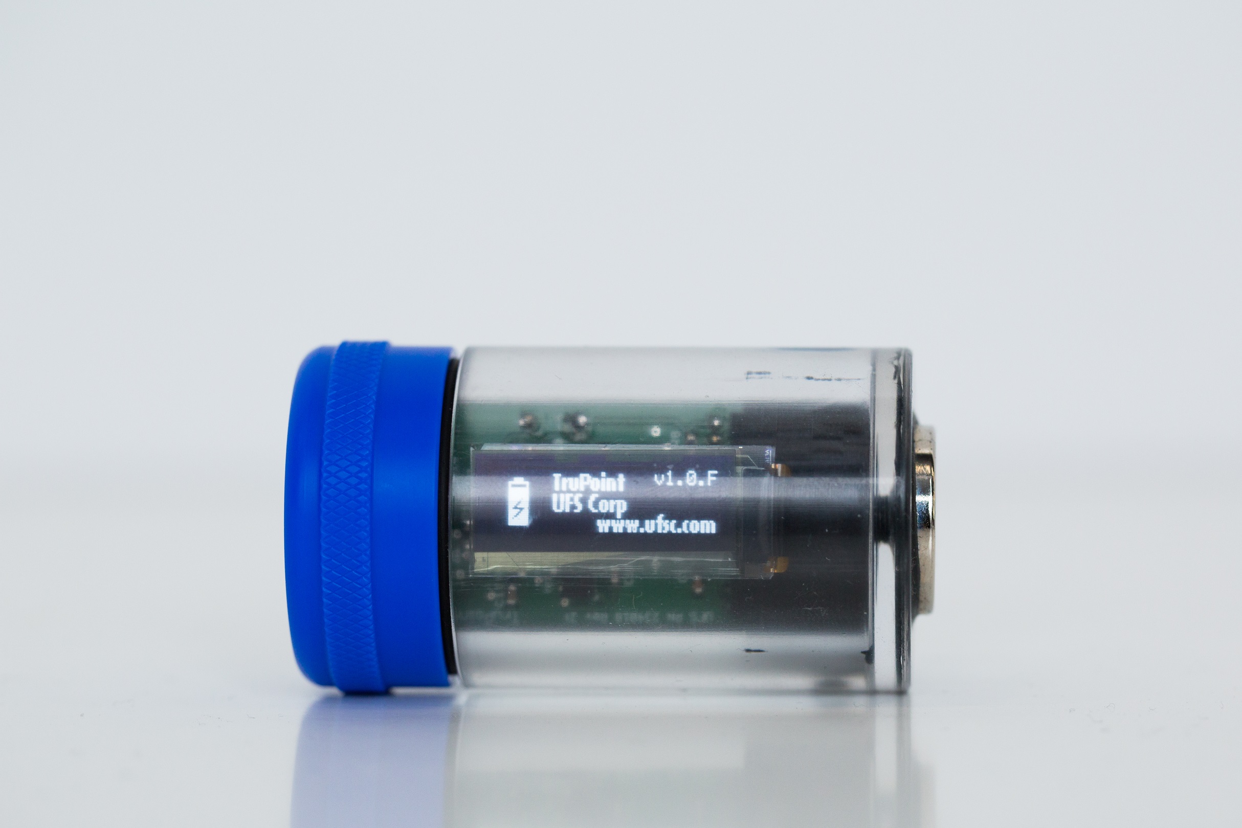
Low Battery Condition
If after waking up the initial screen looks like below, the battery is low and needs to be charged before use.

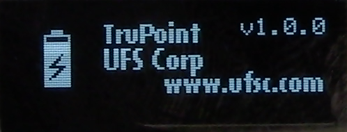
Unit needs to be charged when screen below is shown:

Arming the Logger
The OLED display has to be horizontal and facing upward.
If there is no data or you pressed the Reset button then you should be looking at the 'Ready to Arm' icon shown in the picture below.

If you are successful, then you should you should see the following screen.

If you are not successful, you have to repeat the steps again following each motion.
Place on Ware
At this point you are ready to place the Logger on the Ware and perform the data run. Be consistent where and how the logger is placed on the ware - so future data runs can be directly compared to the runs taken at a later time. Do not place the unit where the Brass Tip is near a hole, curve in the substrate or an edge. The Brass Tip should be placed over a flat portion of the ware with at least a 3 cm x 3 cm area of flat substrate with the Brass Tip in the center of this flat region. The magnet should also be placed on a flat portion so it has a strong hold and is not likely to move. Take a photo of the location to document the position.
Cleaning
After each run the Brass tip and magnet need to be cleared with IPA and the soft nylon bristle brush. Do not use solvents as they will adversely affect the glue used to seal the magnet to the clear body.
Perform 9 V Battery Bench Test
A good place to start is to perform a test at your desk to practice the Arming sequence and observe how the Logger operates. Take the 9 V battery from the carry case and attached the 9 V Battery Cable Leads observing the proper polarity: Red is positrive (+) & Black is negative (-).
Wake the Logger up and wait for to show. Arm the unit as shown above. ![]() will appear when unit is armed.
will appear when unit is armed.
Attach the Black metal alligator clip magnetically to the bottom of the Logger. Then attach the Red metal alligator clip to the Brass tip. You will see the icon change to a pencil. Note - Keep the battery clips attached to the logger for at least 20 seconds. If the test is less than 10 seconds then there will be no temperature results since there is a 10 second delay before the temperature values are recorded.

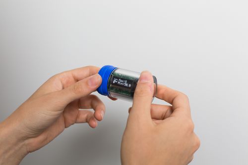
Viewing results
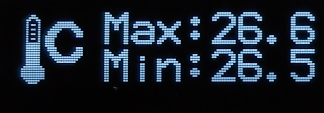
Temperature
Temperature results are shown with Max and Min. The temperature is not recorded until 10 seconds after the logger starts recoding voltages, this allows the thermostat to adjust to the E-coat paint bath after being ambient temperture beforehand.
Voltages
DC Voltage is shown first.

Next AC Voltage is shown. The units are Peak to Peak (not Root Mean Square as typically shown with a handheld AC volt meter). Note the AC voltage measurement is approximate since the sample is far too slow to get an accurate measurement.

AC Ripple Note
AC Ripple % equals AC V (Root Mean Square) / DC V x 100. If your unit has firmware Rev # 1.0.k or earlier, then you can make the calculation manually. For users with firmware Rev 1.0.M or later the next screen shows the approximate AC Ripple %.

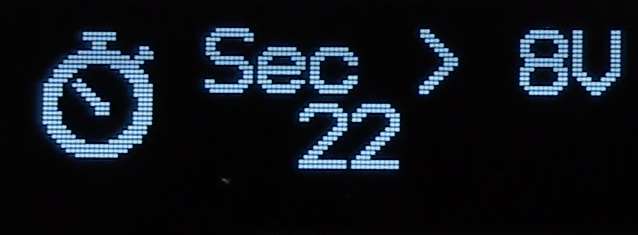
The next time related screen is the area under the Volts Vs Time curve, or Volts * Seconds.

This value is loosley correslated with the film thickness since it Volt*Seconds is an approximatation of the Work performed (i.e. Coulombs). The correlation can be strengthened by holding %NV, bath temperature, line speed, and Voltage constant.
Trouble-Shooting
Cap sEal leaking
100% petroleum jelly (if approved by paint supplier) can be used to help O-ring under blue cap seal better.
Arming the Device
This will usually take a couple of practice tries before you are successful in getting the unit armed. Refer to TruPoint Arming.
Board pulled out when USB plug was removed
This will take some patience but usually it can be performed quickly with no harm done. Make sure the battery is one of the first things followed by the cabling and the printed circuit board. On the upper part of the board are two 'wings' - these are meant to be aligned with the two grooves in the clear plastic body.
Lost O-Ring
A replacement must be ordered and installed before the unit is used again.
Reset
Pressing the Reset button will not erase any previous Run data. Only when the unit is Armed is the previous Run data erased.
Spare Parts List
| Item Description | UFS Part # |
| O-Ring | 565071 |
| Blue Cap | 270072 |
| Universal Wall power adapter | 090535 |
| Micro USB cable | 090537 |
| LiPo battery | 540076 |
| 9 V Battery leads | 073023 |
| 9 V Battery | Z540110 |
| Nylon brush | Z540106 |
| Labels (#1 - #5) | Z150114 |
| Options | |
| 250 V DC + AC Ripple - Calibration Power Supply | 281006 |
| Calibration Cradle | 270302 |
| Alumiunum Panel - Backside Magnet Assist lanyard | 248101 |
Please inquire with your authorized UFS representative below.
Advanced Features
Label CHange
If you ordered just one TruPoint Logger then the label Number will read #1 (i.e. White color). If you ordered more then the following label #/color codes will be used
| 2 | Brown |
| 3 | Green |
| 4 | Yellow |
| 5 | Grey |
Configuration Set-up
In order to start the Configuration menu: remove the Blue Cap and press Button #2 three time within 5 seconds. Refer to the flowchart above for how make selections and move though the menu.
Typically Button #1 is used to increment the selection and Button #2 is used to confirm the selection.
Calibration
Here is a Calibration flowchart.
The first step is to perform a bench top Calibration Run and measure a known voltage,placing the Logger inside an enclosure at a known temperature. Note its best to calibrate for temperature at near what ever the typical E-coat bath tempersature is, say 33 C.
Allow the unit to go to sleep. Wake the Unit up with a tilt and run through the data to insure its close to the values used for voltage and temperature.
In order to start the Calibration menu: remove the Blue Cap and press Button #2 for more than 2 seconds. Refer to the flowchart above for how make selections and move though the menu.
Typically Button #1 is used to scroll through selection and Button #2 is used to confirm the selection.
Options
Calibration Cradle
<<<Add picture>>>
<<<link to Manual/Quick Start>>>
High Voltage Calibration Power Supply
Calibration Power Supply Manual
Aluminum Panels - Backside Assist Magnet Lanyard
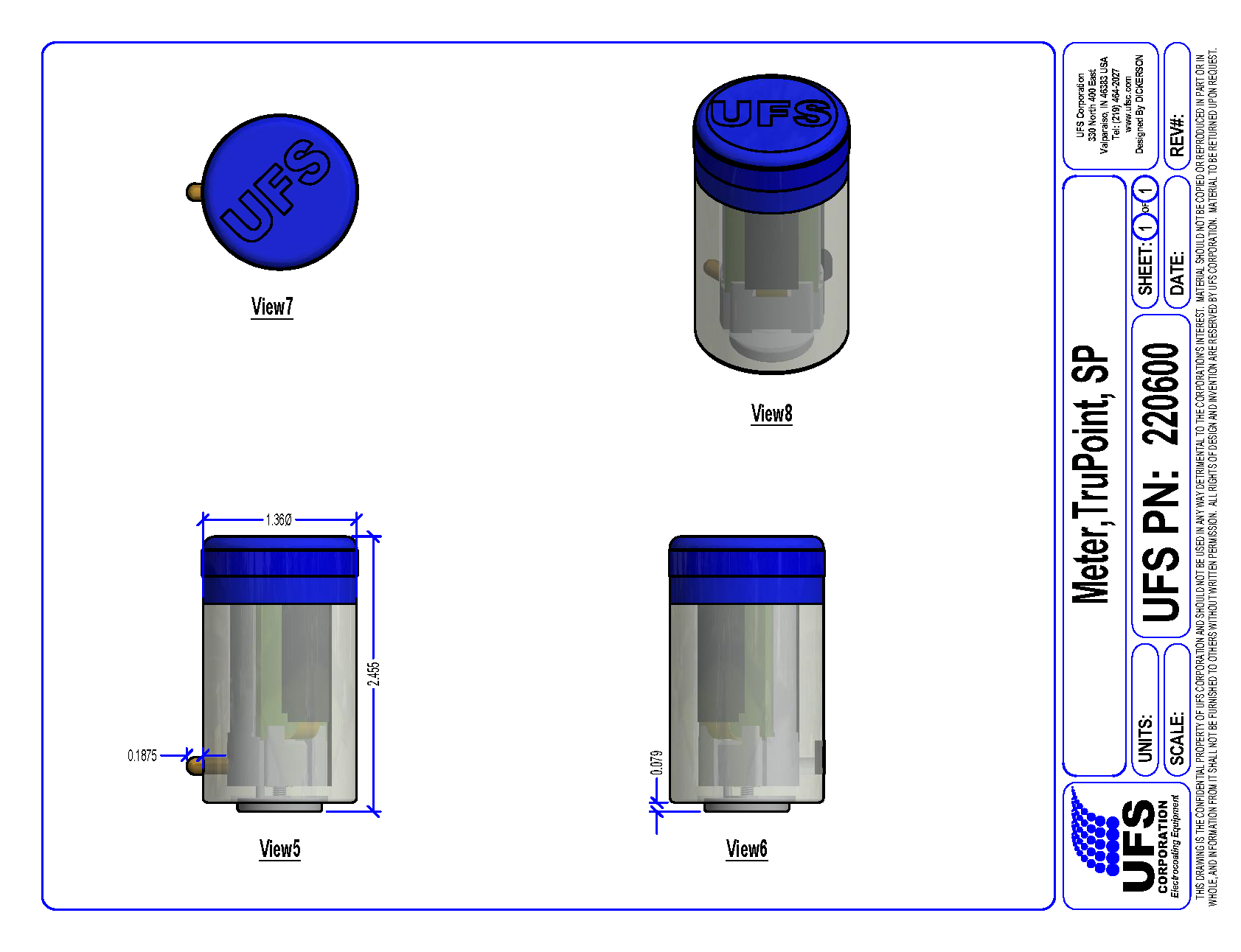
Product Drawing