Stainless Steel Anode Weight Sampling Program
Product Support and Customer Service
For Further support visit our Contact Page
Safety
Think and act in a safe manner. Always disconnect power and use a lockout before you work on the E-coat system, or any of the related subsystems. Observe any confined space conditions. Use the appropriate safety equipment and clothing for the task. Please carefully read all the instructions listed below to familiarize yourself with the project before attempting to perform any of the work.
Required Materials
- none
Required Tools
- Weight scale with 0.1 kg(0.25 lbs) graduations
General
Most materials are sacrificial when used as an anode in an aqueous solution. Knowing this, it is important to estimate the eventual replacement period in order to prepare a maintenance budget. The purpose of this bulletin is to assist with the planning and implementation of a sampling program. For most E-Coat systems there is some symmetry. Anodes are installed down two sides of the E-Coat bath and the ware passes between them. This can help reduce the weight measurement effort. It is not necessary to weigh every anode either. A good sampling program consists of a minimum of six (6) or 10% of the total number of anode cells, whichever is greater. Example: If there were 30 anodes on each side, six should be weighed, since 10% would only be three units.
Procedure
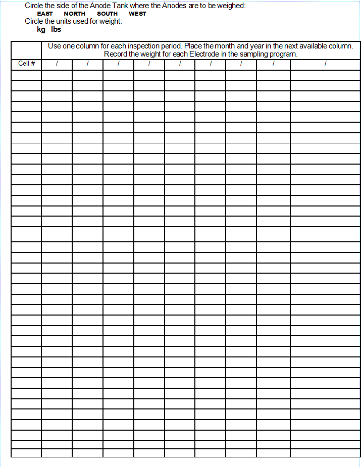
- Select the locations to weigh every six months.
Monorail Systems: Select more in the front, less at the exit, and fewest in the middle. For example, with 30 anodes per side select numbers 2, 5, 10, 16, 26, and 30. (All on the same side of the E-Coat tank.)
Hoist Systems: Due to more even loading of all the Cells, select the ones on the ends and then evenly for the rest. With 20 Electrodes per side select numbers 1, 4, 8, 12, 16, and 20. (All on the same side of the ED tank.)
- To weigh the anode it is not necessary to remove the supply tubing, cable lead, bulkhead fitting (for low profile cells), etc., since the weight of these items will not change over time. Remove the anode, weigh it, and record the weight on the attached form. (Make copies as needed). If you have access to a portable, hand-held scale, then it is not necessary to remove the anode. (Not true for low profile cells.) Attach the scale to the lower hole in the anode tab and raise about 25 mm (1”). The displaced electrolyte will affect the reading, but if the same technique is used each time, it is the weight loss that is important.
- Make a copy of the attached form. Use that copy to record the weight of the selected anodes.
- Anodes should be changed once they have lost a significant portion of their original weight, or if they are beginning to erode at the bottom. Once an anode begins to erode at the bottom, the anode tab will enter the membrane window and it will also wear away. If the tab is allowed to wear away, then the electrical connection will be lost.
- The attached chart (316L Stainless Steel Weight Replacement Chart) shows what the weight will be when 60% of the original mass is lost. You may want to use this as a threshold value that once an anode is at this weight, it needs to be replaced within the next 3 – 6 months time frame. Select the chart based upon the type of anode cell you have. The original TECTRON Anode Cell has an anode with an OD of 48.26 mm (1.900 in). The larger TECTRON Anode Cell has an anode with an OD of 60.33 mm (2.375 in).
- If you begin this process after the system has started up and do not know what the original weight of your anode was, it is an easy matter to reconstruct. The major component is the pipe portion. This can be one of three different types: Schedule 10, 40, or 80. All three of these pipes have the same O.D.
(I.E. 48.3 mm or 1.9”) Measure ID (at the top of the anode): Schedule 10 has an I.D. of 42.7 mm (1.682”); Schedule 40 has an I.D. of 40.9 mm (1.610”); and Schedule 80 has an I.D. of 38.1 mm (1.500”). Refer to the table for the weight/unit length.
- The rest of the anode weight can be estimated by the other items that are attached to it. Refer to the table.
| Weight | |||
| Item | Kg per Meter | Lbs per Foot | |
|
316L Sch 10 (1-1/2”) |
3.13 | 2.10 | |
|
316L Sch 40 (1-1/2”) |
4.08 | 2.74 | |
|
316L Sch 80 (1-1/2”) |
5.46 | 3.67 | |
| 316L Sch 10 (2”) | 3.97 | 2.66 | |
| 316L Sch 40 (2”) | 5.52 | 3.70 | |
| 316L Sch 80 (2”) | 7.56 | 5.07 | |
| 316L Sch 10 (3”) | 6.4 | 4.30 | |
| 316L Sch 40 (3”) | 11.31 | 7.60 | |
| 316L Sch 80 (3”) | 15.18 | 10.20 | |
| 316L Sch 10 (5”) | 11.61 | 7.80 | |
| 316L Sch 40 (5”) | 22.32 | 15 | |
| 316L Sch 80 (5”) | 31.25 | 21 | |
| Kg/each | Lbs/each | ||
|
Supply Tubing 1500 mm (60”) extension |
0.24 | 0.53 | |
|
Anode Tab |
0.15 | 0.33 | |
| Al Heat Sink | 0.03 | 0.07 | |
| 30A Pigtail | 0.015 | 0.03 | |
| 75A Pigtail | 0.050 | 0.11 | |
| 75A Pigtail and Diode | 0.085 | 0.19 | |
| Bolt Set | 0.01 | 0.02 | |
| Bulkhead | 0.55 | 1.21 | |
You can search Amazon.com or a hand held, mechanical weight scale. The model FDK 20 has an upper limit of 10 kg (20 lbs) and the FDK 40 has an upper limit of 20 kg (40 lbs). Note: Select the correct scale for your anode. Typically you want to read a scale in the middle of its range. Make sure that your anode”s weight is not greater than the maximum of the weight scale.
BULLETIN 990129