Leak Checking Anode and Cathode Cell Systems
Product Support and Customer Service
For Further support visit our Contact Page
Safety
Think and act in a safe manner. Always disconnect power and use a lockout before you work on the E-coat system, or any of the related subsystems. Observe any confined space conditions. Use the appropriate safety equipment and clothing for the task. Please carefully read all the instructions listed below to familiarize yourself with the project before attempting to perform any of the work.
Required Materials
- DI Water Source
Required Tools
- Ruler
- Flashjlight
- Graduated Cylinder (20 l - 5gal)
- Screwdriver, crescent wrench
General
Sometimes the Membrane Electrode (ME) System will develop a leak and it will be noticed by the loss of Electrolyte fluid from the Electrolyte tank. Some loss of Electrolyte is normal and this varies from system to system due to such variables as: Cell length and type, ion-exchange membrane, age of the Cells, evaporation, etc. Evaporation is approximately 0.8 l/hr-sm (0.02 gal/hr-SF). Since the liquid level inside the Cell is almost always above the paint level, there is a constant hydraulic driving force trying to force Electrolyte to go through the ion-exchange membrane into the E-coat paint bath. Generally, the ME System may lose up to 20 ml/hr of Electrolye per Cell, depending on conditions.
- Refer to the ME System Schematic before doing any further work to review the entire general flows and the devices found on an Electrolyte Circulation System.
- Check for leaking pipes, connections, and joints and repair as needed.
- Ensure the drain(s) is completely closed. In order to perform the Electrolyte Drawn Down Test, turn off the Electrolyte pump and let the Return Manifold empty back into the Electrolyte tank. Afterwards, measure the Electrolyte liquid level distance from the lip of the Electrolyte tank. Continue with the draw down test until the electrolyte level has fallen 25 mm (~1 inch) or 24 hours has passed. Some amount of loss is normal. If the liquid level did fall, subtract the normal loss for the same time period. If the resulting figure is significant, a leak has occurred somewhere in the electrolyte system. Make sure the drain(s) valve is not cracked open and confirm there are no leaks in the Electrolyte tank. Request Bulletin 990005 for assistance to repair the 304 SS Electrolyte tank.
- Generally, in a Cell with a leak, the liquid level inside the Cell will be the same as the ED paint level. If you can not see the liquid level then it’s likely the fluid was siphoned out of the Cell when the pump was turned off. Investigate the siphon breaker & check valve on the pump discharge piping and correct it.
- Use a flashlight to see inside the top of each T/TG series Cell and make sure the Electrolyte liquid level is at the Overflow Nozzle. For Low Profile Series Cells, request Bulletin 990104.
- Look for evidence of Cells overflowing the top of their necks. The Return tubing should not be kinked, nor rise above the centerline of the Overflow Nozzle. The electrode Tab should not be directly in front of the Overflow Nozzle. Check to see if any clamps are rusted. Rust usually indicates an overflowing Cell.
- Check to see if Electrolyte is leaking out of the Return Manifold Vent, or from a broken Siphon Breaker at the end of the Electrolyte Supply Manifold?
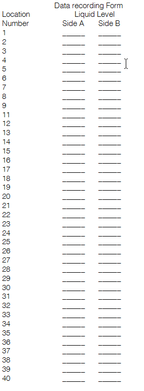
- Turn off the Electrolyte pump and use a flashlight to look inside the Neck (top of the Cell). After one hour, record on a piece of paper the distance from the top of the Neck to the liquid level. Afterwards, subtract the distance from the top of the Cell to the centerline of the Overflow Nozzle. [In most cases, this is 150 mm (6”). If the resulting figure is greater than 100 mm (4”), then remove this Cell and move to Step #9, otherwise you are done.]
- Remove the Electrode and set it aside. Remove the Membrane Shell from the E-coat paint tank and rinse off any paint solids from its outside. Place the Membrane Shell in a 20 l (5 gal) bucket and fill with DI water. Wait 5 minutes and refill to the Overflow Nozzle. Remove any excess water from the bucket and start a timer set for one hour. After the end of the hour, pour any water from the bucket into a graduated cylinder and measure it. Refer to the UFS Engineering Toolkit to see the allowable permeability for your cell size. If it exceeds allowable permeability, then check for possible tears, small puncture holes, or other defects.
- Small holes, cuts or tears in the Membrane Shell may be repaired with PN 540013 (T/TLP series) or PN 540019 (TG/TGLP series).
NOTE: Membrane Guards can be ordered to provide more protection if your Cells do not have them now. (i.e., model numbers beginning with T/TLP).
BULLETIN 990103