Flushable Manifolds
Contents
- 1 Product Support and Customer Service
- 2 Safety
- 3 Required Materials
- 4 Required Tools
- 5 General
- 6 Picture 1
- 7 Picture 2
- 8 Picture 3
- 9 Picture 4
- 10 Picture 5
- 11 Picture 6
- 12 Picture 6-1
- 13 Picture 6-2
- 14 Picture 7
- 15 Picture 8
- 16 Picture 9
- 17 Picture 10
- 18 Picture 11
- 19 Picture 12
- 20 Picture 13
- 21 Picture 15
- 22 Picture 16
- 23 Picture 17
Product Support and Customer Service
For Further support visit our Contact Page
Safety
Think and act in a safe manner. Always disconnect power and use a lockout before you work on the E-coat system, or any of the related subsystems. Observe any confined space conditions. Use the appropriate safety equipment and clothing for the task. Please carefully read all the instructions listed below to familiarize yourself with the project before attempting to perform any of the work.
Required Materials
- PVC Heavy Bodied Primer
- PVC Heavy Bodied Cement
- Spray Bottle Filled with Water
Required Tools
- Torque Wrench
- 2 - 5/16” Wrenches
- 5/8” Wrench
General
Steps in assembling ME Floor Cells. It is suggested that the assembly is done inside of ED tank at the very position it is installed. UFS manufactures both Roof Membrane Electrode (ME) Cells and Floor ME Cells that incorporate a bulkhead to keep the electrolyte fluid inside the portion of the cell with the membrane. A PVC manifold (or conduit) assembly is made to isolate the electrolyte.
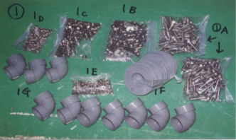
Picture 1
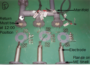
Parts and identification used in this picture document. A. Bolt for flange 5/8” x 3” B. Washer for flange C. Nuts for flange 5/8” D. Lock washer E. Bolt and nut for anode tab F. 5/16” Flange gasket
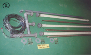
Picture 2
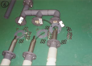
A triple assembly is laid out showing the relationships of each of the parts with each other. Note that the bubble wrap and poly sleeve has been removed to better show the shell appearance but in actual work the cover should not be removed till installation has been completed and anolyte is ready to be re-circulated.
Picture 3
Supply tubing, electrolyte return tubing and electric cable from the ED paint bath.
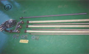
These assemblies can either be single, double or triple. Photos shown denote a triple being assembled. For singles and doubles the same installation method is used.
Picture 4
Bulkhead showing hoses and wires each numbered to identify which one is to be connected to which Cell. The bulk head is mounted on the tank bottom.
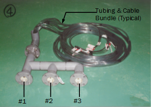
By default the branch (individual ME Shell) farthest away has the highest number.
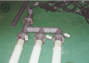
Picture 5
Open the flanged side of Cell cover and pull back so the flange will be exposed. Insert electrodes in as shown. Leave about 185 mm (7.8”) out of the Cell.
Picture 6
Place gasket over end of electrode with tab. Connect electrode power tab connections tabs as show in 6-1. See the difference between 6-1 and 6-2 where the pencil points proper connection is for the electrode’s tab to the inside of the bulkhead flange’s tab and the nut must come inside. Tighten nut securely. If done otherwise the shell side flange and bulkhead flange do not meet properly.
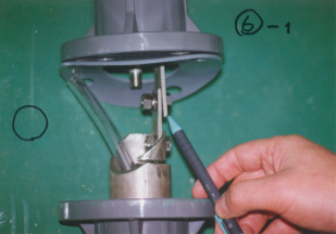
Picture 6-1
Put gasket. Connect tabs as shown in 6)-1. See the difference between 6)-1 and 6)-2 where the pencil points proper connection is for the electrode’s tab to the inside of the bulkhead flange’s tab and the nut must come inside. Tighten nut securely. If otherwise done the shell side flange and bulkhead flange do not meet properly.
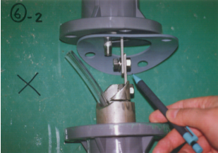
Picture 6-2
Put gasket. Connect tabs as shown in 6)-1. See the difference between 6)-1 and 6)-2 where the pencil points proper connection is for the electrode’s tab to the inside of the bulkhead flange’s tab and the nut must come inside. Tighten nut securely. If done otherwise the shell side flange and bulkhead flange do not meet properly.
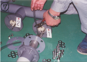
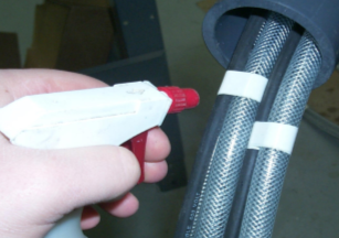
Picture 7
Cut the anolyte supply hose at right length so it is connected to the anloyte supply nipple of bulkhead.
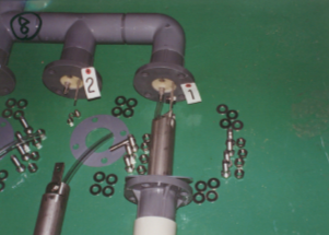
Picture 8
Tabs and hose are connected.
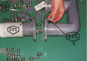
Picture 9
Lift up shell flange and lightly shake as you bring the shell flange against bulkhead flange. Turn membrane shell so the SSS marks on both flanges will meet. By so doing the membrane seam will come faced to bottom of tank.
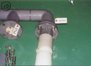
Picture 10
Flanges are fastened together using 4 sets of bolts, washers and nuts. Tighten nuts 1 and 2 evenly, then 3 and 4 and go back again to 1 and 2, 3 and 4 so that all 4 nuts are evenly tightened. (Torque to 25 foot pounds.)
Picture 11
No. 2 and 3 Cells are connected in the same way. Be sure that the drying preventive covers are still over the membrane.
Picture 12
Now run hose and wires through the pipe. Spray water over them to reduce friction. Do not use silicone or other oil because even a minute amount of such material may cause serious painting trouble if they get in the ED tank.
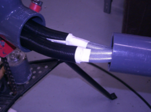
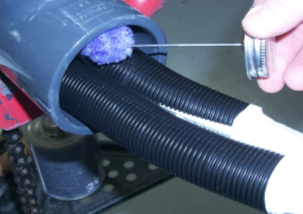
Picture 13
Push hoses and wires into the pipe. Spray water as they go in. (Be careful not to pull on supply and return lines may cause kinking.) Do not remove black wire loom for it serves as a protection against the gluing process.
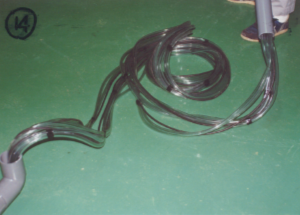
=Picture 14 Threading proceeds. During the threading water is often used as a lubricant.
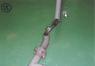
Picture 15
Same as 14 different View
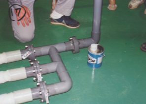
Picture 16
Using PVC primer and cement, the pipe is connected to the manifold as shown in assembly drawing included with shipment.
Picture 17
Assembly Complete
BULLETIN 993413