Field Installation of PN 702028
Product Support and Customer Service
For Further support visit our Contact Page
Safety
Think and act in a safe manner. Always disconnect power and use a lockout before you work on the E-coat system, or any of the related subsystems. Observe any confined space conditions. Use the appropriate safety equipment and clothing for the task. Please carefully read all the instructions listed below to familiarize yourself with the project before attempting to perform any of the work.
Required Materials
- Cell Layout Drawing and Roof Cell Drawing
- See Table Below
| Item Description | UFS PN | Qty / Cell |
| 2-1/2” PVC Sch 80 90 degree Elbows | 806205 | 1 Each |
| 2-1/2” PVC Sch 80 pipe x 20 ft long | 040035 | 15ft (max) |
| 3/8” ID x 9/16” OD PVC Tubing (Supply) | 060001 | 20 ft (max) |
| ½” ID x 11/16” OD PVC Tubing (Return) | 060002 | 20 ft (max) |
| Plastic wire loom | 10 ft (max) | |
| AWG #6 Stranded THHN wire | 240004 | 15 ft (max) |
| #6 round lug for 5/16” bolt | 250017 | 1 |
| 2-1/2” metal 2 piece clamps | 310015 | 2 |
| PVC heavy body cement | Z070005 | as needed |
| PVC cement primer | Z070006 | as needed |
Required Tools
- Screw Driver
- ¼” Wrench
- Pipe Wrench
- 2 (½”) Wrenches
- Bubble Level
General
PN 702028 is the major portion of the Floor Cell. It is shipped without some of the piping, cable, and tubing in order to reduce the shipping complexity and cost. Hence, some field assembly is required for operation. These instructions are meant to provide general assistance and a sequence of preparation and assembly. It is not practical to provide dimensions for each step since most of the dimensions are only know once the Floor Cell’s initial position is fixed.
Step 1
Determine the approximate location for the Floor Cell. See the layout drawing for general guidance. Generally the Floor Cells should be placed perpendicular to the flow of the auto body. If placed parallel to the direction of the auto body, then the Bulkhead should be located on the side towards the exit of the ED tank.
Step 2
Determine how the Cell can be supported on the Cap and the Collar and by two clamps to secure the vertical portion of the field-installed pipe. [See Figure 1.] 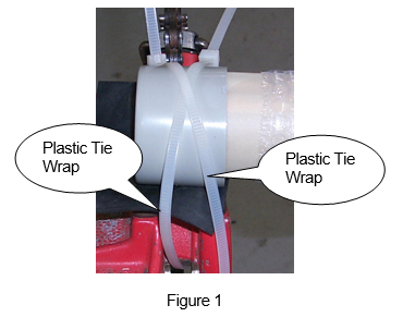
Step 3
If the 2-½” PVC female adapter is attached to the top of the Bulkhead, remove it and set aside. This will make it easier to attach the supply and return tubing.
Step 4
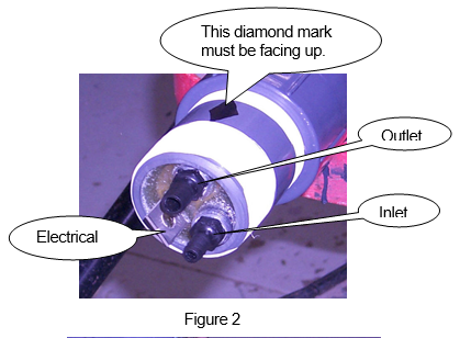
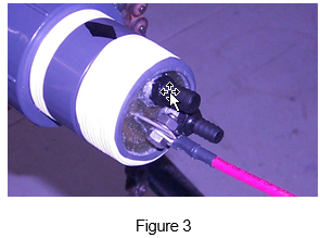
Cut a length of AWG #2 (or as small as #6) THHN, THWN-2, or MTW to length. Place a round lug on one end. Attach this end (with round lug on the electrical connection) to the Bulkhead. [See Figures 2 and 3.] Use the supplied stainless hardware. NOTE: The compression washer must be installed so it goes flat as it is tightened.
Step 5
Cut the 3/8” supply tubing to desired length. Make the cut straight.
Step 6
Dip the cut end into a cup of DI water and push the 3/8” inlet hose barb (smaller and lower hose barb). Push the tubing in as far as it will go.
Step 7
Take the SS clamp and put it over the part of the tubing that covers the hose barb.
Step 8
Tighten the clamp until it is snug. NOTE: If the clamp is not snug, there is a chance that the tubing will come off the hose barb. Do not let any part of the clamp touch the electrical connection.
Step 9
Repeat steps 5-8 to install the ½” ID return tubing.
Step 10
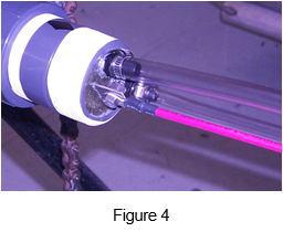
Take note of the location of the outlet Hose Barb. This must be at the 12:00 o’clock position in order for oxygen to be purged. [See Figure 4.]
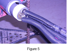
Step 11
Cut three pieces of plastic wire loom about 5’ long (enough to extend past Elbow #1 by 1 foot) and place over each of the Supply, Return, and electric lines. This will protect these items from the PVC primer and glue that can cause problems. [See Figure 5.]
Step 12
After installing the wire and the supply/return tubing, attach the female adapter to the Bulkhead. NOTE: Be sure the Bulkhead does not twist. The diamond on the Bulkhead must always be in the 12:00 o’clock position.
Step 13
Cut a piece of 2½” PVC Sch 80 pipe called out as “Pipe 1.” Glue this into the female adapter.
Step 14
Take a 2½” PVC Sch 80 Elbow and glue on next.
Step 15
Cut a piece of 2-½” PVC Sch 80 pipe called out as “Pipe #2.” Glue this into the Elbow.
Step 16
Raise the unit by supporting at the Cap, Collar, and vertical pipe portion.
Step 17
Hold the unit in place while another person attaches the two plastic wire ties (UFSc PN 245001) over the Cap in an “X” pattern. [See Figure 1.]
Step 18
Place the bubble level on the top side of the Membrane Shell. The Collar end must be higher than the Cap end by 1 or 2 degrees. Add a plastic shim as required. Attach two plastic tie wraps (UFSc PN 245001) over the Collar in an “X” pattern.
Step 19
Attach 3/8” ID Supply line to Flow Indicator (UFSc PN 225044).
Step 20
Attach ½” ID opening in the anolyte trough.
Step 21
Attach the electric cable lead to the appropriate bus bar with a second round lug. If you want to use quick connects or need to use a diode, then follow the instructions called out in Bulletin #993105.
Step 22
After the fluid has been turned on for about 60 minutes, use a flashlight to look inside the vertical portion of the piping and look for evidence of a leak. Repair if needed.