Roof and Floor Cells
Product Support and Customer Service
For Further support visit our Contact Page
Safety
Think and act in a safe manner. Always disconnect power and use a lockout before you work on the E-coat system, or any of the related subsystems. Observe any confined space conditions. Use the appropriate safety equipment and clothing for the task. Please carefully read all the instructions listed below to familiarize yourself with the project before attempting to perform any of the work.
Required Materials
- PVC Heavy Bodied Cement
- PVC Primer
- Spray Bottle with DI water
- Teflon pipe tape
Required Tools Flanged
- Torque Wrench
- 2 x Open end wrenches
- Scissors
- Flat blade screw driver
Required Tools Threaded
- 2 X large pipe wrench
- 2 x Open end wrenches
- Scissors
- Flat blade screw driver
General
Initial installation of the Roof ME Cells should be done immediately before the tank is filled with paint so the ME Cells can be checked for leaks with DI water. The Roof or Floor Cells you ordered can have either a flanged or threaded connection for the Membrane Shell. These instruction will cover both products. If you have a question as to which type you ordered, please refer the your product drawing.
Step 1
Unpack the equipment carefully! Remove any exposed nails or screws from the shipping container which may cause damage.
Step 2
Remove the following item(s) from the container: 3” PVC Header with PVC tubing & electrical cables, Electrode, Membrane Shell & Gasket, stainless steel hardware, wire loom to protect PVC tubing lines, and 3” PVC pipe & PVC fittings.
Step 3
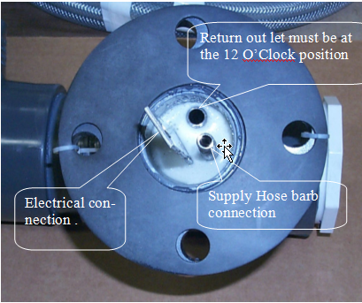
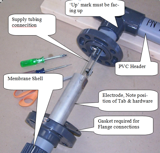
Set PVC Header in position and secure as required to support locations as shown on the product drawing. Make sure the side with ‘Up’ written on is facing up. Take a look at the Bulkhead and you should be looking at something that looks as shown in Photo below. Note there are Left hand and Right hand Bulkheads, but in both cases the Return outlet is ALWAYS at the 12 O’Clock position.
Step 4
After Header is installed, the Electrode is the next item to be installed. You will have to provide some temporary support for the Electrode. Use the 5/16” bolt set hardware included to attach Electrode to bulkhead. See Photo 1 for proper orientation of the Tab of the Electrode and the nut and washer—this must be as shown or the Membrane Shell will not install properly. The compression washer will go flat as it is tightened. If it does not go flat, then you have it backwards. Remove nut and reverse the compression washer & retighten.
Step 5
Trim the PVC Supply tubing that is attached to the end of the Electrode to desired length so it will fit over the Hose barb. Use some DI water to lubricate it and push the tubing over the Hose barb. Use a flat blade screw driver to tighten the stainless worm clamp over the tubing.
Step 6
Place the gasket (flange type) or Teflon pipe tape on the male threads (threaded type) and then slip the Membrane Shell over the Electrode. Secure the Membrane Shell with a temporary support (do not place the restraint anywhere over the membrane portion as this can damage the fragile ion-exchange membrane to keep it from falling a damaging the fragile ion-exchange membrane.
Step 7
Secure the Membrane Shell with Flanges the 5/8” - 11 stainless hardware set (Torque limit is 25 to 30 ft-lbs) or twisting if there is a threaded connection.
Step 8
Remove the temporary restraint for the Membrane Shell and use a permeate support at the PVC cap as shown on the product drawing . Note, oxygen generated on the surface of the Electrode must be able to leave the Membrane Shell and so the PVC Cap of the Shell must be lower than where the Bulkhead is and the slope needs to be about 2% (1/4 inch rise per foot of run). The next step is to extend the 3” PVC pipe (i.e. conduit) up (Roof Cells) and up and over to the rim for Floor Cells.
Step 9
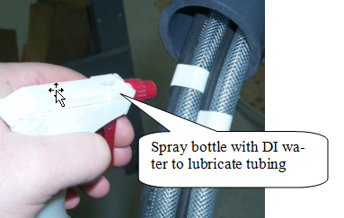
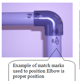
Thread the PVC tubing bundles + electric cables for each of the Branches through the PVC fittings and PVC pipe in the proper sequence using the match marks. Use a spray bottle with water to make the job easier to pull the PVC tubing lines and cables.
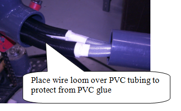
Step 10
Place the wire loom cover over the PVC tubing bundles near the location of PVC Elbows and other fittings where the PVC primer & glue will be used. If this is not done, then damage to the PVC tubing lines can occur. Sometimes the wire loom is pre attached and other times it is shipped loose.
Step 11
The Floor or Roof Cell will typically have 3 Branches. These will be identified as 1,2,3 with the lowest number being the Branch that is closest and the highest Branch being the farthest away.
Step 12
For each Brach make the Supply connection to the electrolyte supply manifold.
Step 13
Next make the connection to the Return Manifold.
Step 14
Repeat for all the other branches
Step 15
Slowing turn on the DI water to the first Branch and let the Membrane Shell fill up with DI water. You should begin to see some DI water in the return tubing after a couple of minutes. After about 30 minutes use a flashlight under each Membrane Shell to confirm that there is no leak.
Step 16
Make the Electrical connection for each Branch.
BULLETIN 993170