Bare Electrode Manual
Product Support and Customer Service
For Further support visit our Contact Page
Safety
Think and act in a safe manner. Always disconnect power and use a lockout before you work on the E-coat system, or any of the related subsystems. Observe any confined space conditions. Use the appropriate safety equipment and clothing for the task. Please carefully read all the instructions listed below to familiarize yourself with the project before attempting to perform any of the work.
Introduction
This manual provides general instructions for: installing, operating, and maintaining TECTRON (both 1-1/2” & 2” sizes) Bare Electrodes. Part Numbers (PN) are six digits long. The last three digits are sequential, while the first three digits designate product line as follows:
724	TECTRON Bare Side Electrodes (1-1/2” Size)
725	TECTRON Bare Floor Electrodes (1-1/2” Size)
726	TECTRON Bare Side Electrodes (1-1/2” Size)
723	TECTRON Bare Roof Electrodes (2” Size)
729	TECTRON Bare Side Electrodes (2” Size)
The Model Number begins with the letters “TB”, like, ‘TB-yyyy-zzzz bbb’. This part number can be interpreted as 'yyyy' equals the effective height in mm; 'zzzz' equals the overall height in mm; and 'bbb' is a designation code for the Electrode material. The part number may also be stated like 'TB-xxxxxx' where the 'xxxxxx' is a reference to the drawing number. TECTRON Bare Electrodes all share some common features, such as:
- Electrodes consist of 304 stainless steel, at the minimum, for duty in anodic ED systems. In cathodic ED systems, the Electrodes are 316L stainless steel, and sometimes more inert materials such as ruthenium oxide-coated titanium or the DurAnode conductive ceramic are used. See the chart below:
| Codes (bbb) | Description of Material | Comment |
| 304 | 304 Schedule 10 stainless steel | Anodic ED only |
| S10 | 316L Schedule 10 stainless steel | Anodic or cathodic ED |
| S40 | 316L Schedule 40 stainless steel | Anodic or cathodic ED |
| S80 | 316L Schedule 80 stainless steel | Anodic or cathodic ED |
| S4S | 316L Sch 40 seamless ss | Anodic or cathodic ED |
| S8S | 316L Sch 80 seamless ss | Anodic or cathodic ED |
| PMx | Precious metal -oxide coated titanium tube | Cathodic ED only |
| Dur | DurAnode conductive ceramic | Anodic or cathodic ED |
- Electrode Holders are made from PVC and other nonconductive, yet durable, materials.
- Orientation
- Bare Roof Electrodes - Horizontal along the top of the ED paint tank.
- Bare Floor Electrodes - Horizontal along the bottom of the ED paint tank.
- Bare Side Electrodes - Vertical along the sidewalls of the ED paint tank.
At the end of this manual you will find General Arrangement Drawings (997139 - Bare Sides; 997138 - Bare Roof; 997136 - Bare Floor). These drawings detail location and placement of the TECTRON Electrodes in your ED paint finishing system.
Safety
A safe work environment for our customers (their employees and outside contractors) is of upmost importance to UFS Corporation. All applicable OSHA and owner’s safety requirements must be followed when performing any maintenance, inspection, repair, or testing on Electrodes and/or Electrode Systems. This includes, but is not limited to, the following safety regulations: Lockout/Tagout (Energy Control); Hazard Communication; Confined Spaces; Personal Protective Equipment; Electrical Safe Work Practices; Ergonomics and Material Handling; Accident Prevention Signs (Danger – Energized Equipment).
Before installing or working on the DC recticifer, Lockout/Tagout procedures are to be followed. Use a Splash Gurad (UFSc PN 175101 or equal) on top of the Electrode Holder with ED tanks that do not have an enclosure wall surrounding the Electrodes.
On-going training of employees on ED equipment and system installation, operation, and maintenance of UFSc components is strongly recommended. MSDS (Material Safety Data Sheets) are provided for UFSc materials. Replacement or missing copies are available upon request from the UFSc Safety Coordinator.
Bare Electrode Description and Function
The TECTRON and TECTRON2 Bare Electrode is used in anodic ED (as the cathode), and in cathodic ED (as the anode) systems. In both cases it serves as the opposing electrode to the ware. Its position and orientation are critical to achieving an uniformly distributed ED film thickness. ED film is deposited according to how much current flows to each section of the ware.
Bare Electrode System Design Recommendations
UFS Corporation makes the following recommendations and guidelines for ED system design. Request Bulletin #991108 for additional information. Please refer to the Figure below as you read this section.
- Electrode Area is estimated by several different techniques, such as: 4:1 Rule; Current Density; Electrode Center to Center Distance; and others. UFSc has an estimating program, and in conjunction with your ED paint supplier, can provide the estimated amount of Electrode area needed for your application.
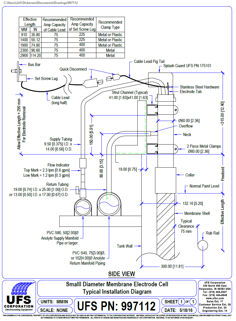
- Cable Leads to individual Electrodes should be designed for 15 amps/m (5 amps/foot) of effective Electrode length (lineal). For example, a typical Bare Side Electrode with an effective length of 1400 mm (55.1 inches) should have cable lead sized for 21 amps. Only stainless steel nuts, bolts, and compression washers should be used. This will help to avoid high resistance problems due to corrosion from less durable materials.
- Enclose the ED tank with an enclosure wall and ceiling to keep employees and dirt out of the ED system. All entry doors must have alarm and lockouts so the DC rectifier is shut down if a door is opened.
- DC Rectifier and Bus Bar system sized according to the specification supplied from your ED paint supplier. Generally, for black or grey cathodic, epoxy-based, ED paints, the DC rectifier is sized by:
Metric: Painted Throughput (sm/minute) x 1.05 [(amp-minute)/(sm-micron)] x ED film thickness (micron) English: Painted Throughput (SF/minute) x 2.5 [(amp-minute)/(SF-mil)] x ED film thickness (mil) Contact your ED paint supplier for representative ED paint data and verification.
- Electrode layout can be adjusted to meet the electrical demands required by the electro-chemical nature of the ED process and the type of conveyor employed to move the ware through the finishing system. Typical conveyor systems used are monorail or continuous motion systems and hoist or indexing systems.
-
- Hoist Systems - Generally hoist ED tanks have an aspect ratio of about 2:1, or more, where the short side of the tank is in the direction of travel and the longer side is perpendicular to the work travel. In this case, the Electrodes are placed on the two longer walls of the ED tank. If, on the other hand, the aspect ratio is about 1:1, then Electrodes are placed on all four walls of the ED tank. In either situation, the Electrodes are usually arrayed over a lineal distance approximately equal to the appropriate plan view dimension(s) of the work package. For example, if the work package is 3050 mm (120 inches) in the direction perpendicular to travel, then the Electrodes (for each side) would be spaced over the 3050 mm (120 inches) distance. Placing Electrodes in the four corners of the ED tank does little good since they are so far away.
-
- Monorail Systems - There should be more Electrodes in the front of the ED system and less in the middle. As a first step, take the Power-On distance and divide by the number of Electrodes on one side of the ED tank. The result should be a center-to-center distance of no more than 600 mm (24 inches). If the center-to-center distance is greater, then add enough Electrodes to lower the average center-to-center to the recommended figure. Once you have enough Electrodes you can begin the layout design. The first several Electrodes should be placed on 150 mm (6 inches) centers; the last two should be placed on 300 mm (12 inch) centers; and the balance spread equally in between.
The first Electrode is generally placed about 10 to 15 seconds further back from where the ware package becomes fully submerged (i.e. Last Part In). This initial dwell time is called Pre Wet because it allows the ware to become completely wet with paint before current starts to deposit any paint solids. This method is called dead entry because there should be little or no current flowing to the ware package as it enters the ED paint bath. Some systems use a live entry, where the first Electrode is located at the LPI point. Regardless of the entry configuration, the last Electrode is generally located at a point approximately where the work package breaks through the liquid level on the exit end (i.e. First Part Out). Refer to the General Arrangement Drawing above to use as an example.
UFSc provides Electrode layout and design assistance at no cost, so please inquire.
- Mechanical support is accomplished with common 41 mm (1.625 inch) square metal strut channels and clamps. Metal two-piece galvanized conduit clamps make installation easy. Two-piece plastic clamps are also available. Fiberglass strut channels are available too. These usually require special plastic clamps.
The strut channels typically are mounted with a 20 mm (0.75 inch) gap between their backs and the tank’s inside wall. The open side of the strut channel is pointing toward the center of the ED tank. The bottom strut channel is mounted immediately above the tank rim (its bottom edge is flush with the ED tank rim) and the bottom of the upper strut channel is usually 150 mm (6 inches) above the ED tank rim. The strut channels should have vertical supports (e.g. steel angle iron) every 1500 mm (5 feet). NOTE: Fiberglass strut channels require more supports. Contact your fiberglass strut supplier for specific instructions.
- Electrical installation involves connecting power from the local bus bar to each Electrode with an appropriate cable lead and the UFSc supplied stainless steel 5/16”-18 threads per inch (English) bolt, nut, and compression washer. The cable lead should be sized by the ED system designer with the expected current draw of each Electrode taken into account, as specified by the paint supplier.
- Instrumentation. Current and Voltage measurement is a powerful tool for troubleshooting and PM activities. There are a variety of methods to measure current and voltage and UFSc offers several different products. Your Sales and Service Engineer can provide additional information.
- Roof and Floor Electrodes. These are placed on the top and bottom of the ware, respectively, to supplement the Side Electrodes. In some cases, especially with densely loaded ware arrangements, these Electrodes can be used to increase the uniformity of the ED film thickness distribution.
- Alternative Electrode Materials. In some cases, there can be a need for a different Electrode material than originally specified. For more information request Bulletin #991104.
Equipment Instructions and Installation Notes
You may also refer to the Quickstart Guide contained in your Getting Started package for additional installation instructions.
After the caustic cleaning of the ED tank the Electrodes can be installed immediately before the tank is filled with paint. The less time the Electrodes are in the tank before the paint fill, the less likely that they will be damaged.
If the Electrode Holders are packed in a crate, carefully remove the lid and any hold-down blocks. Completely remove any exposed nails or screws that might puncture or damage the Electrode Holders. Remove the Electrode Holders. Carefully inspect the Electrode Holders and report any defects immediately to UFS Corporation. Electrode Holders and Electrodes with manufacturing defects will be replaced free of charge by UFS Corporation upon return of the defective item. (Note: Items that are sent back to the Factory for inspection must be sent prepaid and require prior authorization. Contact your Sales and Service Representative or ask for Customer Service.)
Special Note for RuO Electrodes: Use caution when Handling RuO electrodes. The coating can scratch easily, and scratched electrodes will wear rapidly when used. Remove all hand and wrist jewelry before handling RuO electrodes and wear cotton gloves.
ROOF AND SIDE ELECTRODES Suggested Installation Sequence.
- Mount each Electrode Holder to the strut channels with two clamps. Refer to the appropriate mechanical drawing at the end of this manual for additional information (997138 - Bare Roof; 997140 - Bare Side). The Electrode Holders should be spaced over the entire length of the painting zone as per the installation layout, blueprint, or drawing. Generally, the bottom of the PVC Collar for the Bare Side Electrode is placed at the low normal liquid level. Be sure every Electrode has a 75 mm (3 inch) radial clearance from any obstruction attached to or protruding through the ED tank wall. At each end of the Bare Roof Electrode is a PVC Cap and Collar. The Collar is at least 50 mm (2") long and is meant to rest on the support structure. Please consult UFS Corporation and your paint supplier for advice.
- If you purchased Cable Leads from another supplier, proceed to Step 3. If you purchased Cable Leads from UFSc, the Cable Lead Pigtail half of the Cable Lead will generally already be connected to the Electrode. In some cases it needs to be rotated away from the Electrode and tightened. If the Pigtail is supplied loose, connect its round lug to the upper hole in the Electrode with the stainless hardware set provided by UFSc. To make it easier to install the electric cable to the Electrode Tab, use a screwdriver through the lower hole in the Electrode Tab. Wipe any dust, dirt, or grime off the surface of the Electrode.
- LOWER THE ELECTRODE INTO THE ELECTRODE HOLDER SLOWLY! DO NOT DROP IT IN! Dropping the Electrode into the Electrode Holder can damage the Holder. Generally, the Tab of the Electrode extends out the top of the Electrode Holder approximately 20 mm (0.75 inches). If the Electrode projects farther than this, it is not properly seated in the bottom PVC Cap of the Electrode Holder. It is important to seat the Electrode properly to prevent erosion of the bottom edge of the Electrode due to high current concentration. Jiggle and twist the Electrode back and forth until it slips into place. NOTE: For applications in which the ED tank is not inside an enclosure, use a Splash Guard (PN 175001 or 175011) to cover the top of the Electrode Holder. Do not glue the Splash Guard to the Electrode Holder, but point it away from any mist/spray or toward the rim of the tank.
- If Cable Leads were purchased from UFSc, plug the red connector (quick electrical connection) of the Cable Lead Long Half into the red connector of the pigtail. Push together the two halves of the drip shield to protect the plastic housing.
- To reduce the number of connections to the bus bar, UFSc recommends ganging 3-5 cable leads together with a bolt-style copper lug. (Request Set Screw Lug assemblies from UFSc.) Begin with the first Electrode and count back to the fifth Electrode. The lineal distance between the first and the fifth Electrode must be less than approximately twice the length of the entire Cable Lead. If the lineal distance is too great, then you must either order longer Cable Leads or use more Set Screw Lugs. Attach the Set Screw Lug to the bus bar with stainless hardware and the compression washer (supplied by UFSc). Repeat the counting process in order to locate the position of the next Set Screw Lug. Repeat this until all the Electrodes have been grouped together.
- Before the unfinished end of the Long Half Cable Lead is trimmed, allow about 300 mm (12 inches) of slack in the Cable Lead so the Electrode’s position can be adjusted in the future. Strip back the insulation from the unfinished end of the Long Half of the Cable Lead and place into the Set Screw Lug. Gang together up to five (5) Cable Leads into each Set Screw Lug.
FLOOR ELECTRODES Suggested Installation Sequence.
- Mount the Bare Floor Electrode to an insulating saddle, or on top of a length of 100 mm (4”) PVC pipe. Refer to mechanical drawing 997137 at the end of the manual. Mount electrode so that blue mark on electrode faces up. See product drawing 725XXX.
- At each end of the Bare Floor Electrode is a PVC Cap and Collar. The Collar is at least 50 mm (2”) long and is meant to rest on the support structure described in the previous step.
- Lash each end of the Electrode with two plastic wire wraps (UFSc PN 245001). Route the wraps in an “X” pattern over the end of each Electrode. Add some holes to the support structure and pass the wraps through the holes to keep from slipping off.
- If Cable Leads were purchased from UFSc, plug the red connector (quick electrical connection) of the Cable Lead Long Half into the red connector of the pigtail. Push together the two halves of the drip shield to protect the plastic housing.
- To reduce the number of connections to the bus bar, UFSc recommends ganging 3-5 cable leads together with a bolt-style copper lug. (Request Set Screw Lug assemblies from UFSc.) Begin with the first Electrode and count back to the fifth Electrode. The lineal distance between the first and the fifth Electrode must be less than approximately twice the length of the entire Cable Lead. If the lineal distance is too great, then you must either order longer Cable Leads or use more Set Screw Lugs. Attach the Set Screw Lug to the bus bar with stainless hardware and the compression washer (supplied by UFSc). Repeat the counting process in order to locate the position of the next Set Screw Lug. Repeat this until all the Electrodes have been grouped together.
- Before the unfinished end of the Long Half Cable Lead is trimmed, allow about 300 mm (12 inches) of slack in the Cable Lead so the Electrode’s position can be adjusted in the future. Strip back the insulation from the unfinished end of the Long Half of the Cable Lead and place into the Set Screw Lug. Gang together up to five (5) Cable Leads into each Set Screw Lug.
Post Installation Checklist
- Carefully review the General Arrangement Drawing supplied by UFSc, make any necessary changes and return to UFSc so the “as built” drawing for your system can be made and then returned back to you.
- Refer to the Bare Electrode Installation Checklist on Page 20 to confirm proper installation.
Normal Operating Parameters
The smooth operation of the ED system requires a continuous monitoring of the important process parameters. For the Electrode system, these important parameters include;
- Electrode Current Density. This figure is an important indicator because it indicates how hard the Electrodes are working and how long they may last. Typical current densities are 35 amps/sm (3 amps/SF). 50 amps/sm (5 amps/SF) is the maximum.
- Required Voltage. The voltage represents the necessary “electrical pressure” required to deliver enough current in order to deposit a paint film thick enough to meet your specifications. This may start out at 150 V or more for a new ED system. When the voltage gets to above 350 V there can be a significant number of ED film defects.
- Mass Loss of Stainless Steel Electrodes. For cathodic ED systems the anodes are sacrificial since oxygen is created at the surface of the anode (from the hydrolysis of water). Typical mass loss rates are about 20 to 50 grams/Coulomb. Operating conditions, D.I. Water quality, and other local practices combined with certain types of contamination can result in much higher levels of anode dissolution. Request Bulletin #990107 for more information. Cathodes generally retain their original mass and shape for many, many years of operation.
- Parameter Data Collection. A timely and reliable method to collect information on these important parameters is key to establishing process control and creating the base line information from which maintenance budgets can be constructed. Sample data collection/recording sheets are included at the end of this manual beginning on Page 21. You should add these parameters to another more comprehensive sheet detailing the other important ED process parameters.
Preventive Maintenance Checkpoints
The following periodic checkpoints are recommended in order to perform preventive maintenance of your Electrode system.
- Daily
Record the values of the parameters in a logbook during each shift. Use SPC techniques to gain control over the process.
- Weekly
Inspect cable leads, electrical connectors, and clamps for tightness and cleanliness.
- Monthly
Record the current draw and voltage reading of individual Electrode(s) while under the largest load and/or fastest conveyor (lowest cycle time for hoist ED systems). Create graphs, or trend lines, of individual Electrode(s) current and voltage Vs measurement date.
- Semi-annually
Visually inspect the surface of the Electrode for pitting or other unusual conditions. Weigh and record the mass of each Electrode. This effort can be simplified by looking at a few of the Electrodes on just one side of the ED tank. Twist the Electrode 1/3 turn to even-out the wear around its circumference. Check the electrical resistance from the bus bar to the Electrode Tab for each Electrode. (Resistance should be very low, maybe less than 0.2 Ohm.) Refer to the instructions for the DC rectifier, to inspect and service as required. Inspect the grounding shoes and clean and adjust as required to lower contact resistance to less than 0.2 . Clean off the racks/hooks so that the contact resistance is less than 0.2 .
General Maintenance
The routine maintenance required for the TECTRON and TECTRON2 Bare Anode Electrode is minimal. This Section will address the recommended maintenance procedures.
- Electrode and Electrode Holder Removal. To remove the Electrode and its holder for maintenance, inspection, replacement or long-term storage, do the following:
- Never attempt to remove or work on a “live” Electrode. MAKE SURE THAT THE POWER IS TURNED OFF AND LOCKED OUT AT THE MAIN DC RECTIFIER PANEL.
- Unplug the quick-connect connecting the two portions of the cable lead, if used; or remove the cable lead from the Electrode by loosening the bolt set on the Electrode Tab. Do not grab the cable lead to pull the Electrode. This could damage the cable lead.
- Remove the Electrode from its holder and rinse off with permeate and set aside so that it does not fall over. The Electrode may be heavy. Take care not to let it fall.
- Loosen the clamps supporting the Electrode Holder on the strut channels and remove the holder, allowing all the entrained paint bath to completely drain out. Rinse the holder off with permeate and set aside. Take special care to rinse out the inside of the bottom PVC Cap.
- ED Tank Dump. Have one person on each side of the ED tank with a D.I. Water hose spraying down the side walls of the ED tank and the Electrodes and Holders. This will rinse off any ED paints from the surface of the Electrode that would otherwise air dry and increase the electrical resistance. Direct some rinse water inside the Electrode at the top of the Electrode Holder. Finally, pull up each Electrode by grabbing the Tab, about 100 mm, and then use the D.I. Water hose to rinse out the inside of the bottom PVC Cap to flush out any remaining paint solids.
- Long Term Storage. If the Electrode Holder and Electrode are to be kept out of the tank for an extended period, it is best to store them vertically to avoid damage while in storage. Store the Electrode Holder and the Electrodes in a warm, dry, and secure area. Keep the Electrode Holder and Electrode free from dust and dirt.
- Reinstallation of the Electrodes. Installation is the reverse sequence of the removal sequence shown above. Remember to lower the Electrode slowly into the Electrode Holder. DO NOT DROP THE ELECTRODE!
- Installation of Spare Parts. Each new spare parts shipment contains specific installation instructions. Before attempting to install the new part, read the instructions thoroughly, especially any safety related issues.
Recommended Replacement Schedule The typical replacement schedule shown below is based upon previous experience for equipment operating up to or below the parameters described earlier in this Manual.
| Component, Noun Name | Replacement Frequency | Comment |
| Electrode (as a cathode), Stainless Steel | about 8 years | When used in anodic ED paint |
| Electrode (as an anode), Stainless Steel | 2-3 years, or when more than 60% of the original mass has been lost. | When used in cathodic ED paint. |
| Electrode (as an anode only), ruthenium oxide-coated titanium | up to 4 years, or when significant surface pitting has occurred | Ruthenium oxide is coated over titanium. Titanium can decompose, like stainless steel alloys, under certain conditions. Do not use as a cathode. |
| Electrode, DurAnode | about 8 years | Can break if dropped or hit. |
| Electrode Holder | about 8 years | Replace if structural integrity is compromised. |
| Clamp | about 4 years | Replace when there is significant surface rust on the clamps. |
| Cable Lead | about 4 years | Replace if contact resistance is greater than 0.2 ohms |
Troubleshooting
Contained in your Getting Started package is a Troubleshooting Guide for your system. If you continue to experience problems, please contact your UFSc Sales and Service Engineer. Recommended Spare Parts The usable life of individual components will vary with service conditions and internal maintenance practices. Some minimum level of spare parts is recommended. UFS Corporation’s recommendation for spare parts is included in your Getting Started package. [Note: Refer to your General Arrangement and Assembly drawing(s) for original component quantities and your specific individual part numbers. (Part Numbers are 6 digits long.)]
Limited Warranty - Membrane Electrode & Electrode Products
WARRANTY
We warrant all equipment manufactured by us to be free from defects in material and manufacture at the time of shipment for a period of one (1) year from the date of shipment. We will furnish without charge F.O.B. our factory, but will not install, replacements for such parts as we find to have been defective.
This warranty shall not apply to any equipment which has been subjected to misuse, neglect or accident, or has been altered or tampered with, or if corrective work has been done thereon without our specific written consent. No allowances will be made for such corrective work done without such consent. Improper maintenance, deterioration by chemical action, and wear, do not constitute defects. Equipment manufactured by others, and included in our offering, is not warranted in any way by us but carries only the manufacturer's warranty, if any. All electrodes (and or cathodes), of any material, are not warranted by us in any way since they by nature are sacrificial and will erode or corrode away with time.
All warranty claims must be submitted within ten (10) days of discovery of defects or shall be deemed waived. All parts returned for inspection must be sent prepaid. No representative of our company has any authority to waive, alter, vary or add to the terms hereof without prior approval in writing. The foregoing is in lieu of all other warranties (including that of merchantability), whether express or implied. LIABILITY It is expressly understood that our liability, including that for breach of Contract, negligence, strict liability in tort, or otherwise, for our products is limited to the furnishing of such replacement parts, and that we will not be liable for any other expense, injury, loss or damage, whether direct or consequential, including but not limited to loss of profits, production, increased cost of operation, or spoilage of material, arising in connection with the sale or use of, or inability to use, our equipment or products for any purpose, except as herein provided.
BULLETIN 994104