UF Element Installation and Start Up Procedure
Product Support and Customer Service
For Further support visit our Contact Page
General
Please read all the instructions listed below carefully to familiarize yourself with the project before attempting to perform any of the work or unpacking any further
Required Materials
- Clean rags
- Glycerin and/or hand soap + water
- New O-rings (see chart below)
Required Tools
- Thin and stiff flexible U-cup seal installation tool (HE/H) or scissors (HS/H)
- Adjustable wrench
- Gloves
This document is meant to be used as a guideline for installing spiral wound membrane UF (ultrafiltration) Element. The Polyvinylidene Difluoride membrane is cast on a non-woven polyester support backing. UF Elements are either a female permeate type or a male permeate type. The UF Element can have a fiberglass exterior and 2 cup seals (i.e known as a high efficiency, denoted by HE or H in the Model number), several layers of wrap, or netting (i.e. known as sanitary design, denoted by an S or HS in the Model number). Note – sanitary UF Elements can also have a fiberglass exterior and thus would have an ‘H’ in the Model Number. A UF Module is defined as an UF Element installed in an UF Housing.
1. Isolate the UF Module to be worked by following the recommended practice which includes isolating the appropriate Module from the ED paint supply and return manifolds and rinsing as required. Isolate the Module from the permeate manifold as well.
Example of female permeate type:
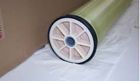
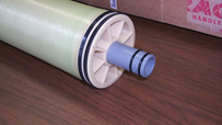
Example of male permeate type
2. Remove the permeate flowmeter assembly from the Top Cap of the UF Housing. Store in a safe place to prevent damage.
3. Remove the top Victaulic coupling from the Housing.
4. Lift the Top Cap off the Housing. In the event that you are replacing an UF Element, in most cases the UF Element will lift up with the Top Cap. If it does not, pull the used UF Element out by the permeate tube extension (or female) or by removing the Housing and bottom Victaulic coupling in order to push the UF Element out from the bottom through the top end. IF your Element uses a separate insert for the lower end of the permeate pipe then keep this part for reuse.
5. Rinse out any ED paint solids from inside the UF Housing with DI water.
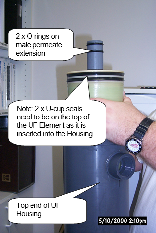
6. Remove the new UF Element from its storage bag making sure that the “O” rings and “U” cup seals are installed in the correct position See the photo on next page for Male Element type, or for Female Element type check Top Cap for proper O-ring position and condition. The permeate male pipe or the female opening needs to be on the top. There should be two “O” rings on the permeate male extension pipe or Top Cap to seal the permeate from the ED paint. There should be two U-cup seals, or else netting on the outside of the UF Element if it’s a sanitary design. UFS recommends replacing the O-rings each time a UF Element is replaced.
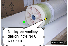
Example of Sanitary design with wrap:
HE/H type with U cup seals The upper U-cup should be installed so the ‘U’ is pointing in the up direction. The lower U-cup should be the opposite where the ‘U’ is facing down. If there are not two “O” rings or two U-cup seals – or the “O” rings or the seals have been cut, torn, or otherwise damaged, call UFS Customer Service and ask for replacement parts. The UF Element could have a cap preinstalled on the other end of the permeate pipe. In some cases, you will need to reuse the lower insert. Use a suitable amount of glycerin to lubricate the ”O” rings and U-cup seals. A vial of glycerin should be included with shipment. If not then use a common hand soap. Do not use silicone-based products for lubrication.
HS/H type with sanitary netting This style does not have a dedicated top or bottom unless the permeate pipe on the one end has been extended and a dome cap factory installed. In this case the insert plug (i.e. Bottom Plug) used on the bottom is no longer required.
7. Fill the UF Housing approximately 1/3 full with D.I. water. WARNING: All rubber seals and “O” rings must be lubricated with glycerin or other non-silicone based lubricant. Prior to installation never use excessive force as seals and “O” rings may get damaged.
8. For HE/H type Elements with U Cup Seals- Insert the UF Element, ‘capped’ permeate tube end (or insert plug) first into the UF Housing using care not to let it drop. When the UF Element contacts the water you may allow it to float down to the point where the “U” cup seal contacts the top of the UF Housing. At this point, carefully push the lubricated U-cup seal into the UF Housing using the thin stiff piece of plastic. Take care not to cut or damage the U-cup seals. Use the same technique if needed for the other seal.
For HS/H type with sanitary netting _ Lift and attempt to install the Element into the Housing, bottom end first, guiding the Element in a circular motion to make sure the sanitary netting stays smooth and tight. If the Element is too large then trim about 150 mm (6”) off of the netting and repeat. Repeat as required until the Element fits snugly into the Housing.
9. Push on the permeate pipe to make sure the UF Element is seated on the inside face of the Bottom Cap.
10. Replace the Top Cap by carefully making sure that the permeate O-rings are properly engaged to their respective bore. Replace the top Victaulic coupling and tighten the two bolts.
11. Replace the permeate flowmeter assembly and tighten the union connections.
12. Fill the UF cleaning tank with D.I. water.
13. Open all ‘permeate to clean’ valves and cleaning return valve.
14. Start cleaning pump and slowly open the cleaning feed valve to the UF Module.
15. Flush element(s) with D.I. water for minimum 15 minutes.
16. Stop cleaning pump and allow system to drain.
17. Close permeate to clean valves, cleaning feed and cleaning return valve. (Note: If you opt to run permeate to drain for the first few minutes, leave the permeate to clean valves open).
18. Open the permeate to rinse valves and paint return valve.
19. Start paint feed pump and slowly open paint feed valve. Adjust inlet pressure to a minimum 50 psi.
20. After the system runs for a few minutes it may be necessary to re-adjust the pressures until the system balances out.
21. If you are running permeate to drain and are ready to change to permeate to rinse, open the permeate to rinse valves before closing the permeate to clean valves. At this point the startup is complete. Record the startup flux rates.
For more information See the original manual that came with the equipment or call UFS.
BULLETIN 993302