TruIDL E-Coat Process Data Logger
Contents
- 1 Product Support and Customer Service
- 2 Introduction
- 3 Different Versions
- 4 Precautions
- 5 USB Encryption
- 6 Known Bugs
- 7 Keys to Success
- 8 What's Included
- 9 Required materials:
- 10 TruIDL Components
- 11 Summary of Features
- 12 Operation
- 13 Configuration
- 13.1 Excel Macro Security
- 13.2 More Macro Security
- 13.3 Location Specific Data
- 13.4 Run Parameters
- 13.5 Sample Rate Selection
- 13.6 Log Trigger
- 13.7 Sensor Specific Data
- 13.8 Zone Specific Data
- 13.9 Update Real Time Clock Calendar
- 13.10 Module & Sensor Harness Serial Numbers
- 13.11 Device Drive Name
- 13.12 Create a TRUIDL.TXT file & Save your DashBoard file
- 13.13 Safely Disconnect from the PC
- 14 Preparing to Make a Run
- 14.1 Safety considerations
- 14.2 Where can the Module & Harness be installed?
- 14.3 Blind Plug
- 14.4 Extension Cable
- 14.5 Protective Jacket
- 14.6 Screw Back on the USB waterproof cap
- 14.7 Placing the TruIDL Module & Sensors on the Ware
- 14.8 Removing the TruIDL Module & Sensors from the Ware
- 14.9 Voltage Sensor Wiring Harness
- 14.10 Pre-plan where each Voltage Sensor will be placed
- 14.11 Secure Ground Connection
- 14.12 Unused Voltage Sensors
- 14.13 USB Connection Abort (firmware 2J/3J or later only)
- 14.14 Final Check before the Run
- 14.15 Attach the Module to Ware & secure with a plastic tie wrap
- 14.16 Double Check Sensor ID #’s
- 14.17 How to Attach the Voltage Sensors
- 14.18 Avoid Close contact with another part of the ware
- 14.19 Sensor tip should not be over a hole or depression
- 14.20 Use a small test panel coupon instead of the ware
- 14.21 Aluminum Panels
- 14.22 After the Run
- 14.23 Rinsing the Equipment
- 14.24 Cleaning the metal components
- 14.25 USB Cable
- 15 Data Retrieval and Viewing
- 15.1 E-coat film thickness
- 15.2 Copy an Old TruIDL File
- 15.3 Edit X Axis
- 15.4 Interpretation of Charts
- 15.4.1 Chart
- 15.4.2 Normal
- 15.4.3 Loss of Ground
- 15.4.4 Indication of AC Ripple
- 15.4.5 Influence of Anode Cells
- 15.4.6 Auto Voltage Control of the DC Rectifier
- 15.4.7 Trouble with a Voltage Sensor
- 15.4.8 Poor Performing Anode Cells
- 15.4.9 Removal of unwanted curves from a chart
- 15.4.10 Horizontal Axis
- 15.4.11 Legend
- 15.5 Report
- 16 Traveling
- 17 Battery Care
- 18 TruIDL Storage and Shipping
- 19 Bench Test Simulation
- 20 Trouble-shooting
- 20.1 Amber LED is Flashing
- 20.2 Default Configuration Parameter Used
- 20.3 Unable to Upload Configuration file to the Module
- 20.4 Visual Basic Error Run-Time ‘52’, or ‘71’
- 20.5 Putting a TU5 Configuration file on a TU10 Module
- 20.6 PC asks if you want to format the TruIDL
- 20.7 Only Red LED On when USB cable is attached
- 20.8 TruIDL Module does not wake up
- 20.9 Low Battery Voltage
- 20.10 Painted/coated Voltage Sensor tip
- 20.11 Loss of Ground connection
- 20.12 Broken/lost Voltage Sensor
- 20.13 Cut/damaged Voltage Sensor harness wire
- 20.14 Type Mismatch
- 20.15 No TRUIDL.TXT is created
- 20.16 Unable to copy & paste the TRUIDL.TXT file to the Module
- 20.17 No TRUIDL.TXT or BAT_X_XX.VLT files are seen
- 20.18 Under Liquid Sense Mode – Module starts to Log when Armed
- 20.19 Corrupted Memory Restore – Firmware Code 2I & 3I or newer ONLY
- 20.20 Sensor is not recording voltage data
- 21 The following items can result in damage to the Module:
- 21.1 Not Having a Secure & Persistent Ground Connection
- 21.2 Do not use metal tools to open the Clear top of Round Housings
- 21.3 Do not Cross Threads of the Clear Top
- 21.4 WIndows Explorer used to Format TruIDL Module
- 21.5 Using Windows Explorer to Delete TRUIDL.TXT from the Module
- 21.6 500V Result
- 21.7 Liquid inside the Module
- 21.8 Frosted module top
- 21.9 Over-exposure to Pre-treatment Chemicals
- 21.10 Bent Pins – Voltage Sensor Harness
- 21.11 Travel through the Oven
- 22 Spare Parts List
- 23 Making Repairs
- 24 Returning a unit for service from outside the USA
- 25 Appendix A: Amber LED Status Codes
- 26 Appendix B: LED sequences
- 27 Appendix C: Specifications
- 28 Appendix D: Data Flow Chart
- 29 Appendix E
- 30 Appendix F – Typical Configuration File
- 31 Appendix G – Typical Run File (Raw)
- 32 Appendix H – Field Calibration Procedure
- 33 Appendix I - Keys to Success with Wire Spool
- 34 Appendix J – Aluminum Adapter Accessory
- 35 Appendix K – TSA & Customs Information Sheet
- 36 Appendix L How to Reset
- 37 Appendix M - Export Goods Back to US for Inspection/Repair
Product Support and Customer Service
For Further support visit our Contact Page
Introduction
The TruIDL Logger is meant to measure voltage near the surface of the ware in an E-coat paint system. Voltage is directly related to the amount of E-coat paint film that has formed directly underneath the voltage sensor. For more information on the purpose of the Logger, visit our website at http://www.ufsc.com/#!truidl/se4ik. Our site offers YouTube videos that also may be helpful, as well as the FAQ section. The TruIDL Logger is battery powered and communications are handled by a USB connection. Microsoft Excel is first used to create a configuration file. Once the file is uploaded to the TruIDL Logger and it’s armed, the Module is ready to begin recording E-coat process data. The TruIDL should be removed from the ware after the last rinse. Run data is downloaded to your PC. Excel is used for viewing and interpretation of the data. There are two cathodic paint versions of the TruIDL Logger: TU5 and the TU10. The differences are detailed on page 8. There is only one anodic paint version and it’s the TU5A. It is the same as the cathodic TU5 except it has a red carrying case and red product markings, so it is easily differentiated.
Different Versions
The manual is meant to cover all the different versions of the TruIDL Data Logger. Several changes have been made to the voltage sensor harness, sensor bodies, and the plastic module case.
TruIDL Classic Logger
Starting in 2Q15 product changed to blue bottom and white round printed circuit board. The other major change was removal of the Smoothing parameter and addition of a User Selectable Voltage Trigger Set point of 5,6,7 or 8 volts.
Voltage Sensor Harness
The early units had the sensor wires made from AWG 22 wire. The insulation jacket could be nicked or cut by the sharp edges of the ware. The new coiled wire is still AWG 22, but its insulation is thicker and made from a tougher plastic material.
WARNING WHEN NOT USING THE LIQUID SENSOR SECURE IT TO ABOVE LIQUID LEVEL OR SECURE MAGNET TO A GROUND!!!
Sensor Bodies
The very first sensor body used a Horseshoe magnet. This style has been obsoleted and replaced with round magnets.
Plastic Cases
The first Module body had a square case made from polycarbonate plastic with four plastic screws in each corner that sealed the case. And the later versions have a round case made from PETG, and a clear top that can be loosened with a strap wrench. The third generation Module body has a blue Delrin bottom and clear PVC top.
Ground Connector
In earlier versions the Ground Connector was a dark green coiled wire with a small alligator clip. If you have a Voltage Harness made from all coiled wire, then the Ground Connector has a tan coiled wire (can stretch out to ~3 m [10 ft]) and a medium-sized alligator clamp.
DashBoard Ver 2.57
The earlier Excel DashBoard (Rev 1.3 and before) was created in Excel 2003 and ported over to Excel 2007/2010. Some users might get the following warning message, which can be ignored (click OK).
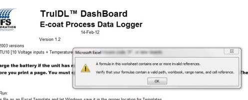
The later DashBoard files (Rev 2 and later) were created using Excel 2013 and this warning no longer appears. Contact UFS for a copy of the latest DashBoard. Note: Excel 2003 will not function with DashBoard Rev 2.0 or later.
With the introduction of the TruIDL Classic Logger there will be a change to the DashBoard since the Smoothing parameter will no longer be supported.
1 . For the original TruIDL Logger users with firmware up to #2K (TU5) or 3K (TU10) or later, you should be using the file called ‘TruIDL DashBoard Rev 2.57.xlsm.’
2. For TruIDL Classic users with firmware 5A (TC5) or 6A (TC10), you should be using the file called ‘TruIDL Classic DashBoard 2.57.xlsm.’
Limitations of the DashBoard
The Dashboard will only support one Extension Cable and just one Protective Jacket. If you have more than or either – then you will have to create another Excel DashBoard for use with the second Extension Cable and/or Protective Jacket. If this is case, then contact UFS Corporation for assistance.
Precautions
- The TruIDL Logger is meant to be submerged for several minutes at a time to an approximate depth of 1 m (3 ft) for a short duration in the E-coat bath. Because the case is made from PVC, the upper temperature limit is 65 C (150 F), the unit must be removed prior to the curing oven stage of the E-coat paint process.
- Since there are so many different chemicals used in the pre-treatment, it’s not possible to test them all for harmful effects on the plastic case. Thus UFS recommends that the Module not be immersed in the pre-treatment stages.
- If your E-coat system is a hoist or square transfer and it’s not practical to attach the sensors just before the E-coat bath, then use a Voltage Harness extension cable and place the Module above the liquid level with its magnets attached to the carrier. The extension cable comes in 1 m (3 ft), or 1.5 m (5 ft) lengths or as required. If this distance is too far, then order the optional Protective Jacket (PN 270300), that encloses the Module and keeps the pre-treatment chemicals from making direct contact.
- Make sure the Auxiliary Ground Clamp is firmly attached to the body (i.e. ware) and there is slack in its cable. If this Auxiliary Ground Clamp comes loose during the data run, damage can occur to the Module.
- Try not to extend the coiled wire to its full length, especially if it will be traveling through the higher temperatures of the pre-treatment system. In some cases, the coiled wire may not relax back to its original tightly coiled state.
- Confirm that the 100% petroleum jelly & the plastic electric tape is approved for use with your E-coat paint supplier. If not, ask them for an approved substitute you can use.
- Solvents (Acetone, MEK, Butyl Cellosolve, etc) should NOT be used to clean any of the plastic, or epoxy/glue parts of the unit.
- UFS recommends using ONLY isopropyl alcohol to clean the metal and plastic parts after a run.
- Use ONLY the included nylon bristle brush on the round magnet face on the back of the Module and on the brass voltage sensor tips. Do not use the nylon bristle brush on any plastic parts or on the glue that holds the magnets on the back of the Module. This will scratch the plastic case and damage the glue joints.
- The magnets will create E-coat paint defects that have to be repaired post E-coat. Each voltage sensor will leave a small-uncoated spot (size depends on the diameter of the attachment magnet) and the Module will leave two uncoated spots, each spot 3.2 cm2 (1.2 in2).
- The magnets (on the back of the Module and in the voltage sensors) should be kept at least ½ m (20 in) away from magnetic records like those found on credit cards. For persons with medical implants, keep the magnets a full meter (40 in) away from any devices.
- Take special care to avoid damage to the insulation of the wire for each of the sensors.
- WARNING WHEN NOT USING THE LIQUID SENSOR SECURE IT TO ABOVE LIQUID LEVEL OR SECURE MAGNET TO A GROUND!!!
USB Encryption
Some corporations use special encryption routines to protect sensitive company data on their company PCs. This could be something like Windows Bit Locker or other third party software. In the case of Bit Locker, when a USB device is connected for the first time, a large file is written to the USB device. If a file is then downloaded to the USB device, the file can only be read by the computer it was downloaded from (or another of the company PCs with the same encryption code provided). There is not enough room in the memory of the TruIDL to accept this large encryption file. You will have to contact your IT Department and ask for an exception to the use of Bit Locker for USB devices with the name ‘TruIDL’.
Known Bugs
Unable to Wake up with Tilt or USB Cable attachment
If you are using a TruIDL Classic Logger with firmware code 5A (TC5) or 6A (TC10), there is a known bug that does not allow the unit to wake up when tilted the exact same time a battery check is performed. You will need to perform a reset. See Service Reference 990409 or Appendix L of this manual.
Wrong battery voltage reported
If your firmware is Version 2H (TU5) or 3H (TU10) or earlier, this applies to your unit. The Module may report a battery voltage greater than 4.2 V, like 8.84 V (shown below) or some other unusual value when the USB plug is first attached.
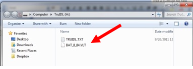
If this happens, unplug the USB cable and wait 10 seconds. Reattach the USB cable and view the files again on the TruIDL device. The voltage will be updated to its present value (4.20 V max).
Time of day
The unit will lose as much as 50 minutes in a 24-hour time span. This is generally not an issue, since the time is used as a date stamp for the time and date that is approximately within an hour of when the unit is prepared to run. The default is ‘Yes’ to update the Real Time Clock Calendar. Then accept the defaults for the Date and Time of day.
Windows v8.1
While testing is done to ensure operating system compatibility, issues do arise. Firmware code “2I” or “3I” may cause a BLUE LED dual flash after the configuration file is uploaded. This is caused by an incorrect memory check. The unit is ok to use and will log data as expected, except it will use a default TRUIDL.TXT file, which may not be the same as what you wanted to use. A configuration error will be reported after the run. To correct this issue, the internal memory needs to be restored to factory settings (see section called Corrupted Memory Restore in Troubleshooting). The TruIDL.TXT file can be modified with a program such as Notepad or WordPad. This file can then be uploaded to the TruIDL Module using the copy and paste method.
Keys to Success
- If the Module has not been used in the last 5 days, the battery must be fully charged before use. Use the supplied USB Wall Charger.
- Make sure the voltage sensor tips have been cleaned. If in doubt (tips look clean and free of E-coat paint solids), use the brush to scrub the brass tips.
- Use a fast sample rate with no over sampling (i.e. Smoothing = 1) for the first couple of runs. This will alert you to any unusual electrical issues with the E-coat paint system. Once the data from these fast sample rates are well understood, the sample rate can be made longer and over-sampling can be employed (i.e. Smoothing Rate > 1).
- Print out a copy of the Checklist and Film Thickness form and take with you.
- Document locations of the sensors with a camera.
- Insure both of the magnets on the back of the Module are on the ware (or carrier – cathode) and the auxiliary ground clamp is attached to the ware too (redundancy).
- Make sure the blue USB cap is fastened.
- Turn auto voltage controllers OFF (i.e. manual operation) and set the voltage set point(s) manually.
- Remove the Module and Harness from the ware before the ovens and clean with IPA
- Once the run is complete, take time to clean the sensor tips and straighten/untangle the wire, so it’s in great shape for the next run.
- If your corporate IT Department uses Windows Bit Locker or some other USB encryption software – you must ask for a waiver from this protocol. Otherwise you will be unable to use the TruIDL Voltage Data Logger.
What's Included
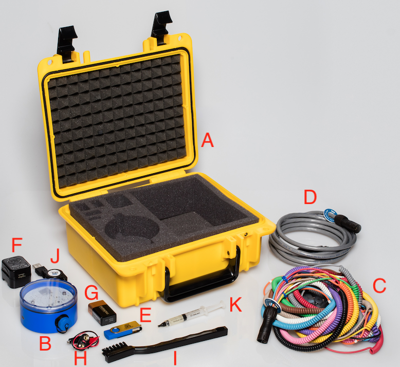
- A - Carrying Case with foam cut-outs
- B - TruIDL Classic Logger
- C - Voltage Sensor Harness
- D - Extension Cable
- E - USB stick that includes manual, spare parts list and Excel template
- F - Universal Wall Charger
- G - 9 V Battery
- H - Alligator Clips
- I - Small Plastic Hand Brush to clean wire parts
- J - Mini USB Retract Cable
- K -100% Petroleum Jelly w/syringe
Included buy not shown - Calibration Report, Blind Plug Adaptor, Aluminum Adapters for Class A Sensor, Voltage Sensor Wire Repair Kit, Quick Start card and Plastic Tie Wraps.
Required materials:
- 30 cm (12”) long plastic tie wraps (to secure the unit via the lanyard to the ware)
- Wire cutters to cut the plastic tie wrap
- Small flashlight to see the color-coded wires
- Bottle of isopropyl alcohol
- Clean 20 l (5 gallon) plastic bucket filled with DI water
- Camera to photo document the sensor locations
TruIDL Components
Summary of Features
| Model Designation | Details | TC5 | TC10 |
| Neodymium Magnet | 2 x 19 mm (3/4”) dia | Y | Y |
| Plastic tie | Opening in Harness SN label | Y | Y |
| PVC Case | Clear Top/Grey Bottom | Y | Y |
| Mini USB w/ Cap | IP 68 | Y | Y |
| Multi-pin connector | IP 67 | Y | Y |
| Voltage Probe Sensors | Y | Y | |
| Attaches to body/ware | Neodymium magnet | 5 | 10 |
| Voltage Sensor Lead L | AWG #22 Stranded | varies | varies |
| Temperature | NTC Thermistor | N | Y |
| Electronics | |||
| 8 bit microprocessor | 12 bit ADC | Y | Y |
| # Voltage Inputs | 0 - 500 V | 5 | 10 |
| # Temperature inputs | 10 - 40 Deg C | n/a | 1 |
| Rechargeable battery | 1800 mAh LiPo | Y | Y |
| 70k Memory | Internal | Y | Y |
| RTCC | Y | Y | |
| Tilt switch | Y | Y | |
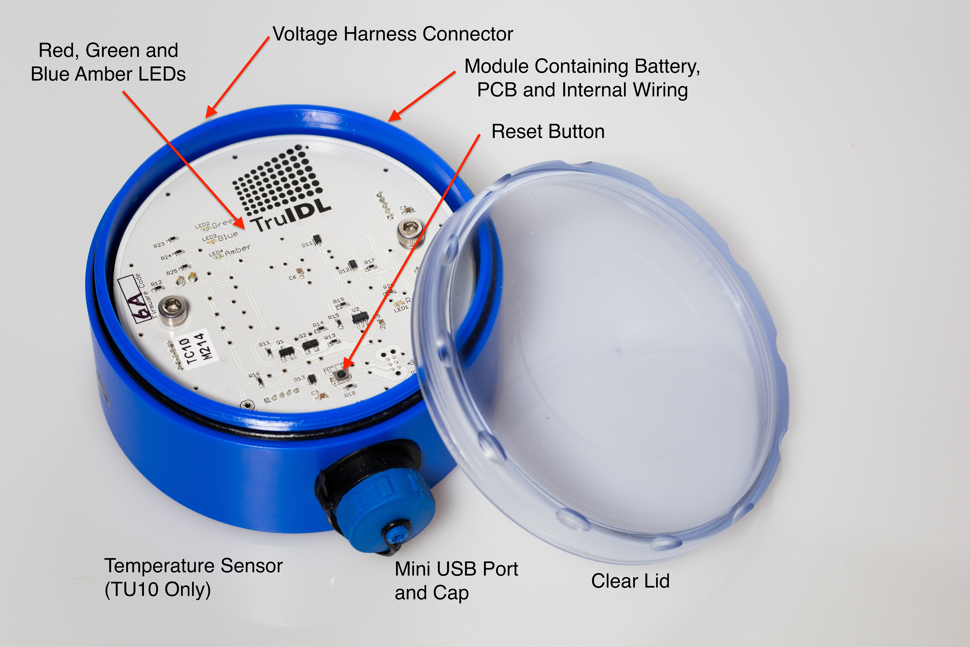
| Indicator | Red, Green, Blue, & Amber | LEDs | LEDs |
| Ground shoe on back | Via magnets | Y | Y |
| Auxiliary Ground clamp | 3 m (10 ft.) | Y | Y |
| USB port | Mini USB | Y | Y |
| Carrying Case | Yellow Cathodic Paints, TU5/10 | Y | Y |
| Red – Anodic Paints, TU5A | Y | N |
Operation
Charging
Charge the battery first via Mini USB cable & USB wall charger. After the Red LED goes Off the battery is fully charged. Disconnect the USB cable from the wall charger. Hold the Module in a horizontal position with the USB connection pointing at you, then tilt it towards you 90 degrees to wake it up and then back to horizontal orientation. The Green, Blue, and Amber LEDs will have blinked just once to indicate the tilt switch had closed. The Amber LED will blink if the battery voltage is below 3.9 V. If the battery voltage falls below 3.65 V before or during the run, logging will not start (may go back to sleep as soon as it is wakened up) or cease, respectively. It is recommended to charge the battery before each run. The maximum battery charge rate is controlled by a chip and is limited to no more than 0.5 amps. Thus the minimum time to charge a fully drained battery is almost 4 hours.==
Viewing the battery voltage
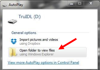
Plug in the USB cable to the Module and your PC. Click on the ‘Open Folder’ to view files.
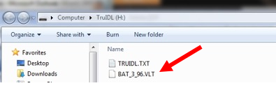
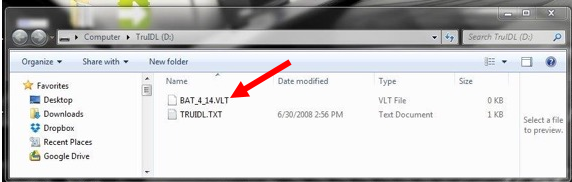
You will see the contents located in the memory of the TruIDL. In the case below, there is TRUIDL.TXT file and a second file called ‘Bat_3_96.VLT. This indicates that the last battery voltage check performed before the USB cable was attached was 4.14 V. To find out the current battery voltage: disconnect the unit from the USB cable, wait 10 seconds, and then re-connect the USB cable. The battery voltage reported now will be a current value. The maximum voltage is typically 4.20 V.
TRUIDL.TXT file
This file at first only contains the basic configuration parameters need to make a data run. When data logging is initiated run data is appended and the file name is unchanged. The file on the unit when you take delivery is the factory default values.
Note the time stamp on the file is 30 Jun 2008. This is not a misprint. It is just the date associated with the default file. There may be times when the TruIDL has to reset its memory and so if yours see this date in the future then you will know the unit has put the factory default values into memory.
Do not attempt to rename or delete this file. Altering the TRUIDL.TXT name will cause the file to reset itself back to factory defaults.
If you want to learn more about what is inside the TRUIDL.TXT file, see Appendix F.
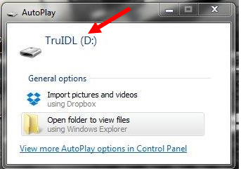
Device Name – TruIDL
When you plug in your USB cable and the TruIDL Logger is recognized by the PC, it will have a name of TruIDL followed by the Drive letter assigned to the USB port. In this case the USB device is referred to as ‘TruIDL (D:)’.
Powering On and Off
If left inactive for a specified time (Shutdown Timer value), the TruIDL Logger turns itself Off to conserve battery power. When Off, all LEDs are Off. As soon as the user wakes up the TruIDL Logger, the green LED will turn On to show “Power On.” The other LEDs may or may not be On (or Blinking). The user can wake up the TruIDL Logger in one of the following three ways:
- Tilting the unit from horizontal to vertical (unit facing towards user) & back to horizontal
- Connecting the unit to a computer via the USB port,
- Pressing the MCLR (master clear) reset switch
Note = the MCLR (i.e. reset) switch is included as a backup feature and is not expected to be used very often. If the battery is at or below its Very Low level, the Module will turn Off as soon as it is awakened. In this case, connect the Module via USB to a computer (or use the USB Wall Charger) and allow the battery to recharge. The TruIDL Logger will never go to sleep with an active USB connection. When just the Green LED is On & not attached via USB, the Module will power down and go to sleep when the ‘Shutdown Timer’ condition has been met. The Shutdown Timer is set by using the TruIDL Dashboard file, and is covered later in the manual. Your TruIDL Logger is delivered with a one-minute Shutdown Timer value. The TruIDL will only cease logging for the following conditions:
- Battery voltage has dropped below the Low, Low voltage level
- Flash memory is full
- Hardware fault is detected
If logging stops for any of the reasons listed, the data collected up to this point can be retrieved.
Switch Action (Tilt)
Every tilt-switch closure causes the Green, Blue and Amber LEDs to flash briefly. This provides visual feedback when the tilt switch closure is attained, as well as a visual test of these LEDs (e.g., when all the warning lights on the dashboard light up when you start a car). The TruIDL Logger uses tilt switch actions when waking up and arming the TruIDL Logger and is only effective along one axis (from horizontal toward you 90 degrees). Once Armed, the tilt switch is ignored and the Module will not go to sleep until:
- USB cable is attached
- The run is completed
- Battery voltage falls below the Low, Low level
- Flash memory is full
- Hardware fault is detected
Modes - Access and Logging
The TruIDL Logger has two modes of operation: Access and Logging. The Access mode is intended for communication with the computer via USB. The user will first upload a configuration file to the TruIDL Logger defining the sampling parameters for the next process run. Once the run has completed, the TruIDL Logger returns to the Access mode so the user can retrieve logged process data from the TruIDL Logger, downloading it to the computer. The Logging mode begins after the TruIDL Logger has been configured, disconnected from USB, armed, attached to the ware, voltage sensors attached as desired, and the voltage sensor wiring harness is connected to the Module. The Module is Armed by a single tilt-switch closure to begin sampling voltage inputs and then starts looking for “live” data. Once “live” data is sensed, data logging begins and will continue until:
- Flash memory is full
- Live data ceases for longer than the InterZone Delay
- Battery voltage drops below the Low level
- Hardware has been detected
The Amber LED will indicate the status of the run (if it is awake) and continue to do so until the Module is connected to the USB computer port. The InterZone Delay allows live data to cease for a short period of time without causing the termination of a logging run. This allows the TruIDL to move from one electrical zone to the next.
Typical Data Logging Session
After the configuration file (TRUIDL.TXT) is uploaded to the TruIDL Logger, the Green & Blue LED will be illuminated, indicating the file’s presence. Disconnect the Module from the computer, and carry it to the ware (Refer to the ‘Preparing to Make a Run’ section for set-up instructions). When ready, tilt the Module once to Arm it. (Once Armed, the tilt switch is ignored until the run completes or the Module is returned to the Access Mode.) The Green & Blue LED will begin to blink every 4 seconds as the logger is looking for live data. Once live data has been found only the Blue LED will blink every 4 seconds. Print out a copy of the Checklist & Film Thickness Form and use this to confirm locations of the Voltage Sensors. At the end of the run the Green LED should be On again (it may have to be tilted once to wake it up), the Blue LED is Off and the Amber LED blinking indicating the status of the run (1 blink for successful run). Refer to the ‘After the Run’ section (further on) for removal procedure and cleaning. Connect the USB cable to the TruIDL Logger, open the Excel file you saved earlier when the configuration file was created. Move to the ‘Run Data’ tab and click the button called ‘Load Run Data’. The run data is shown in tabular form. Click on the Chart tab and then view the data on an X-Y type chart.
Configuration
See Appendix E for a pictorial view of the TRUIDL.TXT file used for configuration of a data logging run.
Excel Macro Security
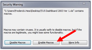
Excel 2003
When you open the file the first time you will see the following window for Excel 2003. Click ‘Enable Macros’ as shown below.
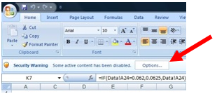
Excel 2007
You will first have to click on ‘Options’ as shown below.
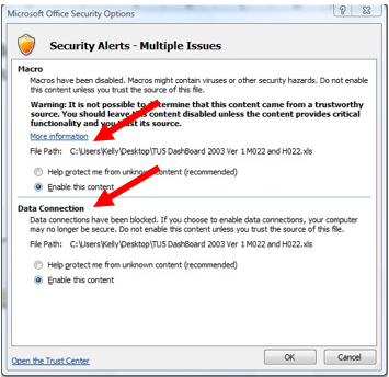
Next you will see another window that needs two selections made in order to allow macros to function. See below.
Excel 2010/3
Click ‘Enable Content’ for Excel 2010 as shown below.

More Macro Security
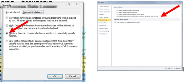
Some users may have to first adjust Excel macro security settings: For Excel 2003 - click on the menu bar: Tools/Macros/Security and then select Medium in order to allow the macros to become functional. In the screen shot below left, the user will get the window like above asking for permission to enable macros (each time the file is opened). For Excel 2007/2010/2013 from the menu bar File/Options/Trust Center/Trust Center Settings/Macro Settings – then select ‘Enable all macros.’
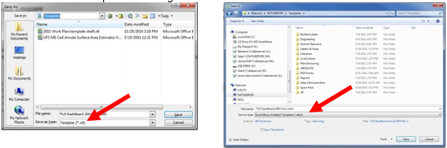
Now you are ready to change the file type to Template (.xlt for 2003 or macro enabled .xltm for 2007/2010/2013). Now perform a ‘File Save As’ and select Template. Save this template in your normal location. We suggest you use a file name like below when you create the template file name - “Your Company Name’ ‘TruIDL Model #’ Dashboard Ver ‘current release’.xlt
Or
“Your Company Name’ ‘TruIDL Model #’ Dashboard Ver ‘current release’.xltm if using Excel 2007/2010/2013. Ask your network administrator for assistance, if needed. Excel 2007/2010/2013 users need to save the file as a ‘macro-enabled template.’ 2003 example is on the left and 2007/20102013 example is on the right below.
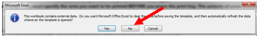
After you click the Save button (above), you will be asked about external data references as shown below. You should click on the ‘No’ response because there is no data relevant yet since no logging runs have been made.
Keep one or more backups of the TruIDL Dashboard file in the event your working copy becomes corrupted. Now you are ready to open the DashBoard for the first time and begin some work. Open Excel. From the menu bar click on ‘New’ and then navigate to the location where your templates are saved. Click on TU5/TU5A/TU10 DashBoard template you just created. Note Excel will append ‘1’ to the name of the template filename so it’s a different file name. You should see the ‘Instructions’ tab when the Excel template file is opened and a fresh copy is created. If you do not, click on the Tab near the bottom edge of the Worksheet called ‘Instructions.’ After reading the instructions, you can click on the Tab called ‘Configuration’ Fill in the fields on the screen. Some entries can be made by first clicking the field, then clicking the drop down arrow on the right corner of the entry box and selecting from the list. Other fields you can enter any number/letter you want; however, if the number/letter is not in the allowable range, an error window will appear and you will be prompted to enter a valid number/letter again.
Location Specific Data
The first section allows you to fill in the run-specific items such as place of test, E-coat tank name, ware description, date, technician, and so on.
Run Parameters
The second section has the logging parameters for the run. In this section, select the Sample Rate (i.e. number of seconds between samples), Voltage Trigger Level, Shutdown Timer, InterZone delay, Temperature units (TU10 only), and Log Trigger (TU10 only).
Sample Rate Selection
When preparing for a data logging exercise, the goal should be to run as fast as possible to collect all the data. However, you also have to consider how much memory is going to be required. The memory space in the TruIDL is about 70 kB which is about 2750 records for the TC5/A and 1300 seconds for the TC10 Modules. Planning for the proper sample rate will ensure a successful run. Look below and using your Power On Time, select the fastest Sample rate.
| Time between samples (seconds) | TC5 (Seconds) | TC10 (Seconds) |
| 0.0625 | 170 | 80 |
| 0.125 | 340 | 160 |
| 0.250 | 680 | 320 |
| 0.50 | 370 | 650 |
| 0.75 | 2060 | 960 |
| 1.00 | 2750 | 1300 |
| 2.00 | 5510 | 2600 |
| 4.00 | 1020 | 5200 |
Log Trigger
There are two methods that logging will commence. Either by User Selectable Trigger Voltage Level or Liquid Sense Trigger (TC10 only).
Voltage Trigger Level
Starting with the TruIDL Classic Logger, the end-user will select the trigger voltage. The default value is 8 V, but 5, 6, or 7 volts can also be selected. Note: the original TruIDL Logger has a fixed voltage trigger level of 8 volts.
Liquid Sense
The TC10 has the option to commence data logging once the ware has entered the liquid E-coat bath. It works by measuring ambient light (LUX). Generally, the Liquid Sense Sensor will be exposed to the florescent light, but once the sensor has been immersed in the E-coat paint, there is a large difference in lighting and so the sensor knows it’s in the E-coat bath and to begin logging data. Note – there may not be enough ambient light in some E-coat systems to use Liquid Sense to trigger the start of Logging. For example, RoDip systems may not have enough ambient light since it’s not common for persons to be front of the E-coat system since the body is so high off the floor. Please follow the instructions below to insure the proper procedure is followed:
WARNING WHEN NOT USING THE LIQUID SENSOR SECURE IT TO ABOVE LIQUID LEVEL OR SECURE MAGNET TO A GROUND!!!
1. Allow the unit to go to sleep before moving it (make sure to set the Shut Down timer to 1 minute). Do not Arm the unit until Step #5. Hold it horizontal at all times until it is armed and then placed on the body. 2. Attach the harness to the TruIDL Module.
3. Take the grounding clip and attach it to a suitable ground point on the body.
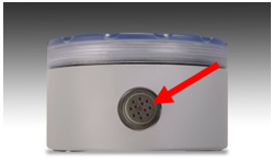
4. Take the Liquid Sense Sensor and attach it to the very front most portion of the body. Orient it in such a way that ambient light falls on the sensor. See picture below
5. Once Step #2 through #4 are complete you can wake the unit up with one tilt. Then the second time you tilt the unit will Arm. The Green and Blue LEDs should be flashing every 4 seconds. If just the Blue LED is flashing every 4 seconds, then the unit has started recording data – see the Trouble Shooting section “Liquid Sense Log Trigger– Blue LED Flashing” for resolution.
In some cases, there maybe 100 seconds or so of no or little activity if the body is fully submerged a far distance in front of the first anode cell. You may want to edit the X Axis of the chart to remove some of the zero activity. See Data Retrieval and Viewing later in this manual for suggestions how to do.
Sensor Specific Data
The next section has a field for naming the location for each of the voltage sensors. Click in the field and select from one of the many choices. You may have to change some of these names (i.e. location labels) after the voltage sensors have been placed on the ware. If you want to create custom locations, click on ‘Sensor Locations’ tab. In the purple section of this worksheet are all the default locations. You can create custom locations by over-writing the existing locations with the one(s) you want.
Zone Specific Data
The next section is the Zone information. Enter the voltage of the Zone 1 DC rectifier and the number of seconds the ware is located in Zone 1. If there is a second zone, enter the DC rectifier voltage and number of seconds the ware is in Zone 2 and so on as required. If there is a ramp period before, just add this to the steady state voltage. For example: rectifier starts at 0 V and ramps up to 180 V taking 15 seconds. It then stays at 180 V for 105 seconds. In this case the Zone 1 voltage is 180 V and the Zone 1 duration is 120 seconds (i.e. 15 + 105 seconds).
Update Real Time Clock Calendar
This defaults to ‘Yes’ each time in order to keep the clock as accurate as possible. Make sure to upload the file within 1 or 2 minutes to transfer an accurate time to the TruIDL module.
Module & Sensor Harness Serial Numbers
The next section is reserved for the serial numbers of the TruIDL Logger Module (on the product label on the left hand side or on the face of the blue printed circuit board) & the Voltage Sensor Harness (scribed into the plastic circular connector housing or on a round label). Select the Serial Number of the Voltage Harness (if you only have one then no further selection is needed) you intend to use. If you are not using the Extension Cable, then make sure it says ‘Not Used’ otherwise select using the drop down box. The same goes for the Protective Jacket too – if you are not using it, then it should say ‘Not Used’. Note – the Extension Cable cannot be used at the same time as the Protective Jacket. Only one of these can be used at a time. Once the harness configuration has been selected the appropriate calibration file is used.
Device Drive Name
The default name of the device is ‘TruIDL’ (without quote marks). If you have renamed your module, then enter its new name. You can use Windows Explorer to discover its name. This completes the configuration process.
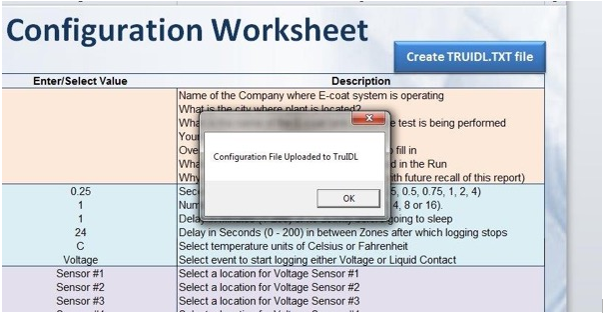
Create a TRUIDL.TXT file & Save your DashBoard file
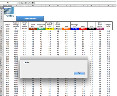
Once the ‘Configuration’ tab is completed, go back to the top of the worksheet and press the ‘Create TRUIDL.TXT file’ button. The file is then created and uploaded to the module. You should see a dialog box below. Click OK to dismiss. The Blue LED on the TruIDL logger should be On now and it is ready to be armed as soon as the USB cable is removed.
These configuration parameters tell the logger how to capture the data during the next logging run. Now save the Excel file using a new name. Choose a name descriptive of this particular run and/or date. To save the copy, choose 'File', then 'Save As' and assign the new file name. It must be different from the TruIDL Dashboard file name; otherwise you will have corrupted the TruIDL Dashboard template.
Safely Disconnect from the PC
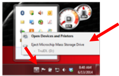
Use the USB Disconnect Utility in the Windows Tray (i.e. short red arrow) to properly disconnect the USB cable BEFORE you pull the cable out. Select the one that says ‘Eject Microchip Mass Storage Device’. Wait till you see the window that say ‘Safe to Remove.’, then pull the USB cable from the PC.
Preparing to Make a Run
Safety considerations
Ware is placed on conveyors that move it through the various stages of the E-coat paint process. These conveyors are very powerful and there are many tight spaces where injury can occur.
Where can the Module & Harness be installed?
In many automotive E-coat paint systems (RoDip systems are an exception) there is well-lit vestibule just before the E-coat tank. This is a good place to work. Sometimes the body is off the floor by a meter (3 ft.) or so, and a ladder is needed. There is moving equipment, so follow the plant’s safety protocol. In the event there is no safe place to install the Module & Harness just before the E-coat tank, then there are several options to consider. It is necessary to stop the conveyor carrier to install the equipment and then a little bit less time to remove it before the ovens. If the time required to stop the conveyor is too much, then the Blind Plug method is a good one to consider.
WARNING WHEN NOT USING THE LIQUID SENSOR SECURE IT TO ABOVE LIQUID LEVEL OR SECURE MAGNET TO A GROUND!!!
Liquid Sense (i.e. contact) Trigger – If you plan to use the Liquid Sense trigger method then you cannot use the Blind Plug Method. Use either the Extension Cable or the optional Protective Jacket explained further below.
Blind Plug
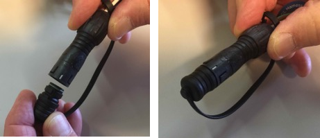
In square transfer hoist and programed hoist type E-coat systems, there is no vestibule just before the E-coat tank. The only place to mount the Module and Harness might be the load station at the front of the E-coat machine and prior to the cleaning and Pre-treatment system. The method involves attaching the Voltage Sensor Harness while the body or the ware is located in the bank or holding area before the Pre-treatment load station. The sensors can be installed in 2 or 3 minutes and usually the body can stay in one place this length of time. The Module is NOT installed at this point, but the Blind Plug is inserted into the Harness circular connector to keep it dry. To make the connection: align the keyway of the Blind Plug (which is not marked with a white mark) and match it up to the white mark of the circular connector, which is the mating keyway. Refer to the photo on the left below. Once the Plug is installed it will look as in the photo below on the right hand side. The completed circular connector and Blind Plug can be left near a front door window opening so it can be quickly located and grabbed.
Once the body or ware reaches to just before the E-coat tank it is time to make a quick change. This will take about 10 seconds. Grab the connector/plug and remove the plug (it’s held on a tether) and then attach the Module. Arm the Module and place it on the inside of the floor plan or the inside of door such that both of the 20 mm (3/4”) diameter magnets on the back of the Module are on a flat and smooth surface and the Module cannot be moved.
Extension Cable
If this is the case, then use the Harness Extension Cable and locate the Module (make sure it is Armed first) on the hanger so both magnets on the back of the case are secured to the steel carrier hanger & above the liquid level so it is not immersed in the pre-treatment stages. Consider using this method if you want to use Liquid Sense. Make sure to follow the proper steps for using Liquid Sense as shown in the section entitled ‘Liquid Sense’ under ‘Log Trigger’.
Protective Jacket
If the height of the conveyor precludes the Extension Cable, then order a Protective Jacket (PN 270300 made from PVC) and put the Module inside. Then the Protective Jacket can be immersed in the pretreatment liquids. Note: it is imperative that the Auxiliary Ground Clamp be attached to a suitable place on the body or ware and that it does not come off. If the ground connection is lost, then the electronics can be damaged very easily.
Screw Back on the USB waterproof cap
Make sure the gasket is inside the Blue cap (see the photo below).

Apply a little of the 100% petroleum jelly to the face of the gasket to aid with sealing the connection. Add some petroleum jelly to the male threads to in order to keep paint solids from penetrating and the drying out, which can keep the cap from fully seating.
Placing the TruIDL Module & Sensors on the Ware
You need to be able to stop the conveyor as it is dangerous to attempt to place the voltage sensors on a moving object, especially if the ware has sharp edges that can cut. If the ware or the rack used to hold the ware is tall, use a ladder and have another person hold the ladder as you carefully place voltage sensors in high locations. WARNING WHEN NOT USING THE LIQUID SENSOR SECURE IT TO ABOVE LIQUID LEVEL OR SECURE MAGNET TO A GROUND!!!
Removing the TruIDL Module & Sensors from the Ware
After the last rinse stage, there may not be as much space or room, so motion is more limited and the space is tighter. The lighting may not be as good and there is probably more water on the surface and so it’s slippery too. All these make for a dangerous working environment. Ask another person to hold the flashlight and a third person to stay near the conveyor stop/start control.
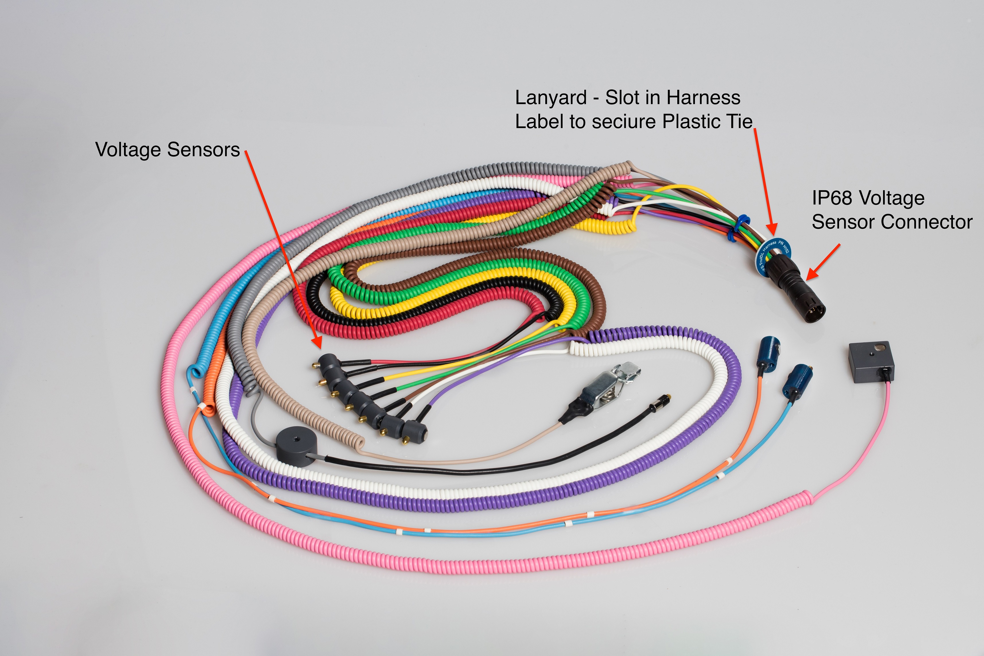
Voltage Sensor Wiring Harness
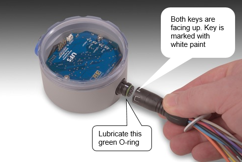
The circular connector (for the voltage sensor leads) attached to the module has a key way at the 12 o’clock position when viewed from the front. In the photo below, the key on both parts is identified with a small white mark. The mark on your Module may not be there because it’s covered over or cleaned off. Even though the white mark is gone you will see a short depression in the plastic (part of the harness) and on the matching connector installed into the Module. Before you make the connection, you should apply a small amount of the 100% petroleum jelly on the O-ring of the circular connector every other run or so. The matching portion of the voltage sensor cable lead has a single short indentation (key) and this must be at the 12 o’clock (when viewed head on) position. Press firmly to seat the two halves together. Take care to align them and do not use too much pressure to join them until the pins and their respective holes are aligned. It is possible to bend the pins if the halves of the circular connector are not aligned properly. WARNING WHEN NOT USING THE LIQUID SENSOR SECURE IT TO ABOVE LIQUID LEVEL OR SECURE MAGNET TO A GROUND!!!
Pre-plan where each Voltage Sensor will be placed
Print out a copy of the ‘Checklist & E-coat Film Thickness’ tab. It has the locations for each sensor that you selected earlier. It also has generic figures of a car body and a wire frame for all other ware types. Take this printout as a reminder of where each sensor is to be placed. If changes are made before the run, then be sure to record them on the form and update the appropriate field(s) in the Excel file’s ‘Configuration’ tab. Consider the location of each sensor and its distance from the Module. Make sure there is enough slack in each voltage sensor to extend (plus some slack) to each desired location on the ware.
Secure Ground Connection
The TruIDL Logger has 3 ground connections. Two are the 20 mm (3/4”) diameter magnets on the back of the Module case. The third is the Auxiliary Ground Clamp - make sure it (tan coiled wire with alligator clamp) is attached to the ware and will not come loose during the painting cycle. Without a good ground connection, the logger will not operate properly and damage can occur from stray high voltage to the electronics.
Unused Voltage Sensors
If there are more voltage sensors than needed for the ware, you have several options. The first option is to place them close together on the ware and ignore the results. It’s possible to remove the curves from the chart, too. Make sure to place them so the magnet is touching the ware. Otherwise if the brass tip touches the ware, the tip will be painted and you have to be careful to clean the tip off before the next use or this sensor will not record data (i.e. the E-coat paint insulates the tip). If you find yourself with unused sensors, then you should consider ordering another harness with the optimum number of sensors for your ware package.
USB Connection Abort (firmware 2J/3J/5A/6A or later only)
If the unit is tilted and Armed and you decide or realize a run cannot be completed, then just reattach the USB cable (from the PC) and this will abort the data run. You will see the Blue LED flash twice and once the USB cable is plugged the Amber LED will flash 5 times. This is normal as the configuration parameters have been reset to their default values. If you want to use other parameters, then just upload the TruIDL.TXT file as you did before.
Final Check before the Run
Is the Module armed (i.e. are the Green and Blue LEDs flashing every 4 seconds)? Is the blue cap screwed back on the USB connection? If the Module’s case has been opened recently, are the two halves tight? You can do a quick check with your fingernail. There should be no gap between the top and bottom halves.
Attach the Module to Ware & secure with a plastic tie wrap
Secure the TruIDL module on a flat portion of the ware near its center making sure both magnets are firmly attached and cannot be pulled off. A plastic tie wrap can be secured to the small slot in the Harness Serial Number label for extra protection, if so desired.
Once the Module is Armed, input from the tilt switch is ignored. Thus the Module can be placed in any orientation on the ware: upside down, facing downward, on its side, etc. It’s helpful during the first couple of times to orient the Module so the LEDs can be seen once the ware leaves the E-coat bath (looking through an access window). Maybe you will be able to see just the Blue LED will flash (it has started logging data) once or twice before it is submerged below the liquid level.
Double Check Sensor ID #’s
Do a double check of the location for each of the voltage sensors just before releasing the ware to travel toward the E-coat tank. Mark any last minute changes on the ‘Checklist & Film Thickness’ printout. It’s a good idea to document the test with a camera to record the locations of the voltage sensors. The TruIDL Logger is now ready for a run.
How to Attach the Voltage Sensors
In many cases the sensors can be placed on relative flat surfaces. Even if the sensor is able to rotate around, as long as the separation distance from the ware to the sensor tip is the same, there should be no effect on the voltage measurement.
Avoid Close contact with another part of the ware
What will cause a problem (i.e. not able to use the data from a sensor) is if another part of the ware is able to make contact with the sensor tip. This is especially important when placing the sensor in a recessed region. If the sensor tip touches the ware, then the voltage will read zero. This is because the reference point is also ground. It’s like you place the red and black probes of the voltmeter on ground – there is not difference in this situation. If the sensor tip is closer to another part of the ware, then the results will not be repeatable as the next time you place the sensor in this recessed area, the sensor tip will be measuring the voltage to the ware ‘underneath it’, which will be farther away than the run before when the sensor tip was placed too close to a perpendicular portion of the ware.
Sensor tip should not be over a hole or depression
The brass sensor tip needs to be located over a flat portion of the ware away from any holes or depressions that will increase the distance from the sensor tip to the ware.
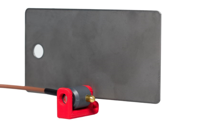
Use a small test panel coupon instead of the ware
There will be a paint defect on the ware from the voltage sensor. It’s not very large, but it’s a defect that has to be repaired. A method to avoid this is to put the sensor onto a bare panel. Ground the panel to the ware or part hanger and place the panel/sensor in an area of interest. The benefit is the ware does not have a defect and it’s quite easy to measure the E-coat film thickness on the flat panel. Maybe you have a tubular ware or uneven ware that would not lend itself to attachment of the sensor in the usual fashion.
Aluminum Panels
If some or all of the body is made from Aluminum, then an alternate strategy is needed. Supplied in yours was 3 different Aluminum Adapters for use with Class A type sensors. See Appendix I for more information on the different sizes. These adapters need a hole or thin edge to attach to. If this is not possible, for example you want the middle of the exterior door, then another method must be employed. If you are faced with this – please contact UFS. There are some methods that use another magnet on the back side of the panel. In this case the Aluminum Adapter is not used and the two magnets attract each other.
After the Run
After the last sensor has left the E-coat bath & the InterZone timeout has occurred, the Green LED will be On and the Amber LED is flashing about once every two seconds. You might have to wake the unit up if it has gone to sleep. The Module and Voltage Sensor Harness must be removed from the ware after the last rinse and BEFORE the oven. Use a wire cutter to remove the plastic tie wrap. Grasp each of the voltage sensor bodies and remove from the ware. Keep the wiring harness attached to the Module. Drop the Module and the sensors into a large bucket of DI water and keep wet until it can be cleaned. Take the Logger in the bucket of water to the E-coat lab. Rinse off the Module and the wiring harness assembly. When ready to disconnect the wiring harness from the module, grasp the long portion of the connector with one hand and hold the module with the other hand. Gently rock the connector back and forth and pull apart at the same time. Wire management is an important task, especially with the TU10. Do not allow the sensors to become entangled together. You will be thankful for the time spent on this task. Do not allow water to enter the exposed metal contacts of the circular connector (of the harness) or the other half of the connector in the Module. If water gets into the circulator connectors, use some clean low pressure air to blow the water out.
Rinsing the Equipment
After a run, rinse the TruIDL in a (20-liter bucket) with either DI/RO water. Do not use a solvent to irrigate or wipe as it will damage the polycarbonate case. Make sure magnets on the back of TruIDL case are cleaned before making the next run.
Cleaning the metal components
It will be necessary to clean the metal Ground Clamp, brass voltage sensor tips, and magnets. Use ONLY isopropyl alcohol. Do not use any solvent as it will harm the plastic, wire insulation, and epoxy components. Use the small nylon bristle brush provided to assist as required.
USB Cable
To access the USB port, unscrew the protective blue cap to expose the Mini USB port, as seen in the photo below. The USB logo on the cable’s connector should be facing up when the Module is lying horizontal.

Data Retrieval and Viewing
Connect the TruIDL Module to a PC with a Mini USB cable. Open the same Excel file as used to create the configuration file. Click on the ‘Run Data’ tab. Then click blue button called ‘Load Run Data’. You will see the screen flash as the TRUIDL.TXT is opened up and its contents imported from the TruIDL Module. Part of the import process is scaling the data to its proper value plus applying the factory calibration factors. Click the Ok button to dismiss.
E-coat film thickness
Every attempt should be made to measure the E-coat film thickness near the location of each voltage sensors. The cured E-coat film thickness is generally loosely correlated to the total area under the curve of Voltage vs Time. Enter the E-coat film thickness after the ware was curved by recording the data on the Checklist & Film thickness tab in the Excel file and save again.
Copy an Old TruIDL File
One way to save time is to reuse old TruIDL DashBoard files. You already have the customer information and the Sensor locations top. You will have to change the date & time. Also change test description and ware too. The old run data will be removed before the new run data is downloaded after the logging run.
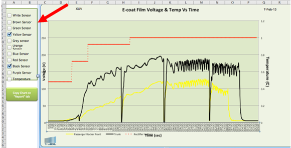
Edit X Axis
Sometimes you may want to edit the X axis to focus on a particular section or remove some zero activity at the start of the cxurves. In the chart below you can see that the voltage only begins to rise after 150 seconds or so.
In Excel you can right click on the X axis and enter the start of the X Axis. Also you can change the number of tick marks and labels to make it easier to read too.
Interpretation of Charts
In the section below, some of the more typical types of charts will be shown and explained.
Chart
In some cases, you will have to alter the format of the horizontal axis to reduce the number of tick marks, so the time can be seen easily. You may also have to select the legend box and make it shorter so the sensor labels are below the title of the horizontal axis. The chart below is from DashBoard Rev 2. Some of the other charts are from earlier versions of the DashBoard.
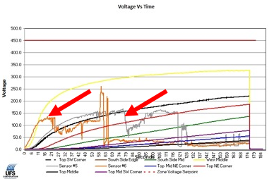
Normal
Normal looking Voltage vs Time curves begin near zero, increase with time, and generally have a nice smooth characteristic. The voltage sensors placed on the outside (i.e. are closest to the Anode Cells, source of the DC voltage) of the ware will reach the highest peak first. Sensors placed in the recessed portion of the ware will take longer to reach their peaks. In the chart below, it takes about 75 seconds before the last of the curves begin to raise upward – these are the most interior of the voltage sensors.
Loss of Ground
In the chart below, from about 121 to 132 seconds, all the voltage curves descend all together. This is indicative of a loss of ground. Such loss can be an issue with the ground shoe, or the design of the hanging point, especially for light sheet metal parts that can be moved around by a mis-aimed eductor jet. It could also be from a conveyor line stop, too.
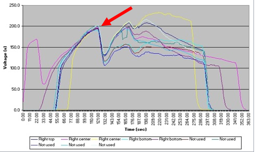
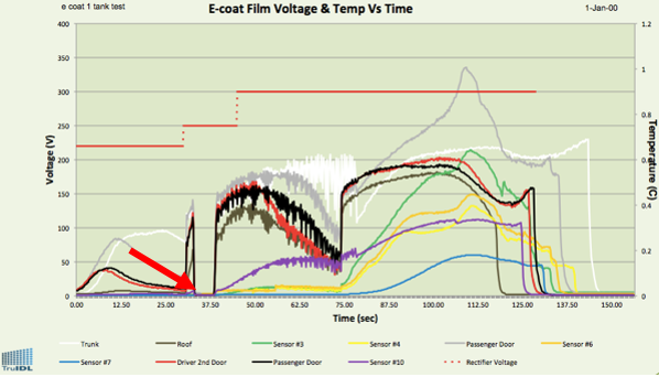
Another example of a Loss of ground can be seen below from about 32 - 38 seconds. In the case all the sensors when to zero in unison, which indicates the ware lost ground for a short while.
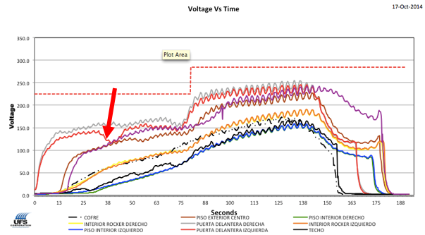
Indication of AC Ripple
The voltage set point as 180 Volts. The readings range up to +/- 80 V, or so. AC ripple should be below 5% and ideally it should be less than 1%. In this example, the AC voltage is ~80 V and the calculation is expressed as AC voltage / DC voltage x 100 = 80 V / 180 V x 100 = 44%. Note: In the chart below an auto-voltage control system was employed. These auto voltage systems adjust the voltage many times a second to limit the total current flow. If you can limit the total current flow, then you are also controlling the E-coat film thickness too. In adjusting the voltage so often to control the current, there is bound to be some differences when compared to the chart with a normal rectifier.

The example above is a rather extreme example of AC Ripple, more commonly it will show itself as an undulation up & down from the prevailing trend line. In all the curves below there is an up and down voltage movement. This is indicative of AC Ripple.
Influence of Anode Cells
In the Chart below in the 2nd Zone is a periodic movement of the Black curve shows the influence of large anode cells. As the ware moves close to the anode cell it shows a slight rise in the voltage, but as the ware moves away the voltage falls off and the cycle is repeated several more times as the ware moves past the other anode cells.

Auto Voltage Control of the DC Rectifier
If your E-coat system uses some sort of auto voltage control, you will need to disable it for the run and go back to manual voltage control. If you left the Auto Voltage Controller On during the run, you would not know the set points the controller used and the data would not have much value.
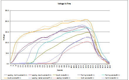
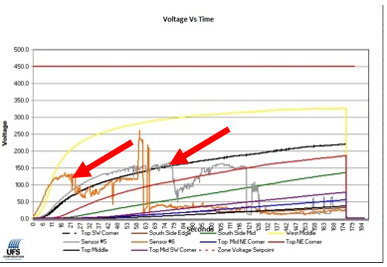
Trouble with a Voltage Sensor
In the chart below there are two curves (Grey & Orange) that reach a peak (very early on during the E-coat paint cycle) and then fall off. This can occur because the wire insulation was cut by a sharp edge of the ware and a path to ground allowed current to flow – thus paint formed on the brass tip. The E-coat paint insulated the tip and the voltage fell down.
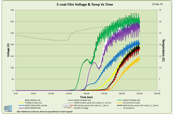
Poor Performing Anode Cells
The curves should be smooth & upward trending as time proceeds, which indicates the Anode Cells are providing the proper and un-interrupted supply of voltage. As the E-coat film builds up its thickness, the resistance also increases, which causes the voltage to increase. In the chart below, the yellow curve is left-door center and it is an example where a ‘poor’ Anode Cell creates an interruption and voltage is lost while the sensor is in front of this poor Cell. It dips at 126 secs, 426 secs, & 451 sec. The Cell(s) at these points should be checked. Replacing these Cells is recommended if no electrical or anolyte fluid connection issues are found, especially if the Membrane Shell is old. There are two zones in this tank. The change over from one zone to the next occurs at about the 276 second mark as all the curves dip at the same time. This is a normal occurrence.

TIP – use Liquid Sense Log trigger to gather more resolution to focus better on where the poor performing anode Cells are located. The Liquid Sense Log trigger will cause the TruIDL Logger to begin logging as soon as the front bumper (where the Liquid Sense sensor is typically placed). You can mark the location of this point on the edge of the E-coat tank. By knowing the conveyor speed you and the number of seconds (from the start of logging) you can estimate the distance of the problem cell from the point where the sensor was first submerged.
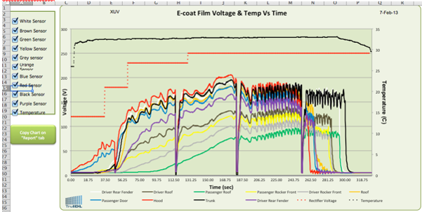
Removal of unwanted curves from a chart
In this example only the Yellow & Black curves are shown. Use the check boxes on the left hand side to make your selection.
Horizontal Axis
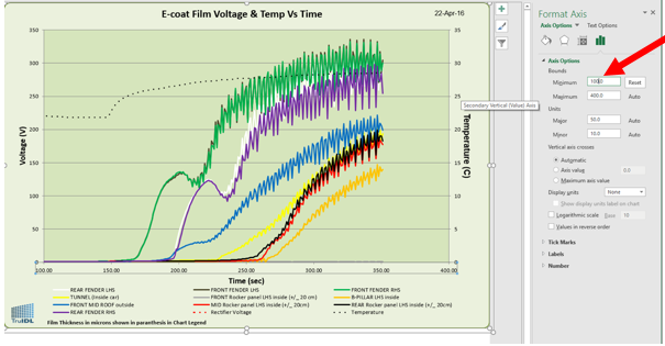
Sometimes the horizontal axis needed to be reformatted to make it easier to see the ‘seconds’. In the chart below the numbers are very close together and hard to read. In some cases, the numbers are lying over each over and very hard to read. Your version of Excel may look different from the screen shot below.
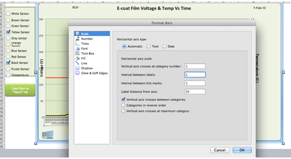
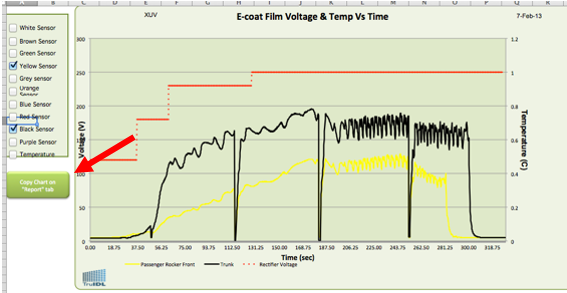
Place the cursor over the numbers of the horizontal axis and do a right click and select ‘Format Axis’. To put some white space between the numbers, use ‘75’ as the ‘Interval between labels’. See below to see the seconds are easier to read than earlier.
Legend
In some cases, you may have to use the cursor and select the Legend to resize it. Once you are satisfied with the Chart, press the green button on the left side called “Create Chart on ‘Report’ tab”. A copy will be pasted on the Report tab.
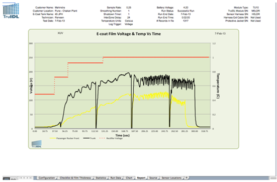
Report
The report is a one-page summary of the test run and can be printed as hard copy for your records or to include in your written report.
Statistics
The Statistics Tab provides at a glance some important information for each sensor. Here are some of the more important ones:
- Max V – Maximum voltage
- Volt * Sec – estimate of the area under the curve, this has a weak correlation to Film thickness and can be improved with some investigation and study
- Delta V – this is the difference from the max rectifier set-point and Max V for each sensor
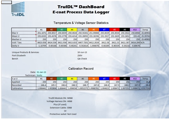
Delta V
This is a very important statistic since it’s a measure of the ‘voltage push’ coming from the anode cells. The higher this number is the better since it means ‘less voltage loss due to poor or old Membrane Shells. Since the ion-exchange membrane’s resistivity increases with age and operation, Delta V tends to increase with time. Generally, Delta V is only looked at for the sensor that is placed nearest an anode cell. So on a car this would be a fender or door.
Delta V / Gap distance
This parameter uses Delta V (from Statistics) and is divided by the gap from the outmost placed voltage sensor and the closest anode cell. For example, let say the Delta V was 34 V and the Gap distance was 39 cm. The ratio would be 34 V / 39 cm or 0.87 V/cm. For most E-coat, the ratio will increase and by the time the ratio begins to exceed 3.0 most systems will show signs of E-coat paint film quality issues.
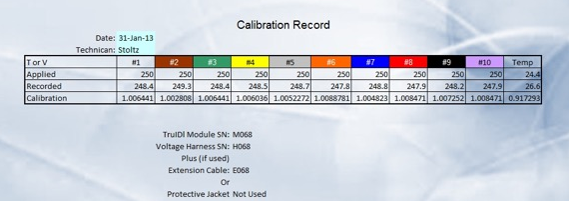
Calibration
Calibration is performed at the factory with the TruIDL Module and the Voltage Sensor Harness and is specific to the combination of these two items. If in the future you have to change either one, then you should return the Module or Harness (item to be used again) for re-calibration. If you have a high voltage DC rectifier, then you can perform the calibration yourself, if so desired (see Appendix G). The screen shot below is from the ‘Data’ worksheet. This is where the calibration data is entered just once.

The screen print below is from the lower half of the ‘Statistics’ Tab. It is simply a record of the factory calibration step. This is a double check to make sure you selected the proper Voltage Harness (most will start off with one harness but may add another at some later point).
Traveling
When transporting the Module, use a Shutdown timer value of 1 minute. That way if the Module is tilted, it will only stay On for one minute and then turn Off to save the battery from discharging.
Airlines & Air Transport
The TruIDL Logger can be placed in your checked luggage. Included with the order is a plastic coated sheet that should be placed near the carrying case in your luggage. It is meant to assist the TSA or customs agent with a description and function of the logger. The lithium ion battery is a nominal 1800 mAhr @ 4.2 volts, which is smaller than the battery in many smart phones today. However, when you ship by air, you need to declare there is lithium ion battery included and provide the battery details shown above. Also you need to declare there are magnets in the device too, but the gauss field is far less than the maximum allowable. See the full details in the TSA & Customs sheet, which is in Appendix J. When shipping by air, the two labels below or their equal should be used. These can be purchased from LabelMaster.com . Magnetized material is label #L19 and the Lithium battery label is #L535. Note – the lithium battery label below is filled out for the previous battery. As of 1 Jan 2012 the capacity of the battery was increased to 1800 mAh. So the label should read 1.8 amp-hr @ 4.2 volts.

Battery Care
The best practice is to recharge the battery before each use if it is not used very often.
Recharging the battery
The Amber LED will blink a relatively long blink when the battery needs recharging. To recharge the battery, if you connect via USB to the computer, it may take 5+ hours to fully charge, based upon what other USB devices are plugged at the same time. The USB wall charger may take up to 4 hours. The Red LED will light and stay lit until the battery has been fully recharged.
Replacing the battery
If the battery fails to hold a charge, it must be replaced. Contact UFS for instructions. Typically, it must be returned to UFS Corporation for replacement of battery.
Do not dispose of batteries in the trash.

TruIDL Storage and Shipping
When storing or shipping the TruIDL Logger, set the Shutdown timer parameter to a low value, such as 1 minute. If accidentally activated, the Module will not remain on for very long, conserving battery power. WARNING: The TruIDL is meant to be stored in its carrying case. The carrying case can be on its back or resting upward (black handle facing upward). In either configuration, the tilt switch will be open and the Module will not wake up. If the Module is stored so the USB connector is facing downward, the tilt switch will be closed and the Module will stay awake.
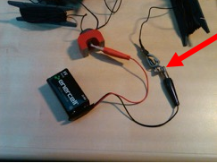
Bench Test Simulation
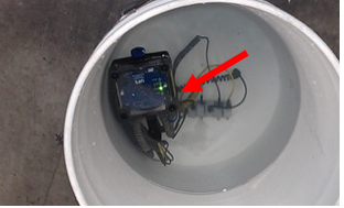
It is possible to set up the Module and simulate a live run by using a 9 V battery. Create a configuration file with the sample period of 1 second. Upload this configuration file (save an Excel file called ‘bench test’ or similar) to the Module and arm it by tilting. Attach the negative clip of the 9V battery to the ground clamp and the positive clip of the 9 V battery to the white wire voltage sensor brass tip (i.e. #1). See below for an example how to connect the 9 V battery (red arrow on auxiliary ground clamp along with the black lead [negative] from the battery).
The Green LED should stop flashing and only the Blue LED should flash about every 4 seconds. Wait about 5 seconds and move the red alligator clip to the brown wire voltage sensor tip (i.e. #2). Wait 5 seconds and then continue with the green, yellow, grey, (TU5 you are done, for TU10: continue) orange, blue, red, black, and purple. Disconnect the red and black alligator clips from the 9 V battery and set aside. There will be a delay based upon the InterZone parameters for the Module to stop recording. At that point, only a solid Green LED will appear and the Amber LED should have a single flash once every 2 seconds. This indicates a successful run. Download the TRUIDL.TXT file into the C:\TruIDL folder. Navigate to the View Data worksheet of the Excel file and press the grey button to ‘Import Data from Run’. The purpose for the bench test is to make sure the module is able to start recording and each of the voltage sensor leads is working properly.
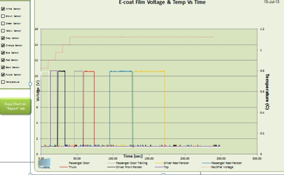
In the plot above, you can see that the white sensor was the first, the brown was the second and so on. If one of the voltage sensor leads does not record, perform the test again. When you perform the test again, make sure to grab the tip of the suspect sensor and twist the alligator clips to ensure a good contact. If the re-test shows the same result, contact UFS for consultation. Note: in the plot above, a red dashed line can be seen. Only integer values can be entered into the voltage set point(s) in the Excel dashboard Configuration tab.
Trouble-shooting
Amber LED is Flashing
The Amber LED will be flashing if some issue has come up. See Appendix A for a list of the codes.
Default Configuration Parameter Used
If wanted a Sample Rate of 1 second between samples and up loaded the TRUIDL.TXT file to the module and made the logging run, but the Sample Rate used was 0.25 seconds per sample. Then it’s likely the TRUIDL.TXT was corrupt or became corrupted when it was sent over to the module. Before firmware Ver 2J (TU5) or Ver 3J (TU10) there was no obvious warning of a problem with the configuration parameters. In order to see the Source worksheet (use the macro “Toggle_Source_Tab” and you will have to enable the Developer function [so it shows up on the Excel menu bar first).
If you see the date of 21 Jan 2011 under the word “No”, then a default parameter value has been used. In the screen shot (top part of the Source worksheet) below is a blue box with an arrow pointed at it. “21” is the day if the month, “1” is the month, and “2011” is the year.

Something is creating a problem with a value written in TRUIDL.TXT or when it’s being uploaded. Ask UFS for assistance. Blue LED Double Flash (firmware 2J, 3J, 5A, 6A, or later) The Blue LED will have a single flash when it is logging (note – Green LED is also Off). If the Blue LED has a double flash and the Green LED is On, then there was an error in one or more of the configuration values in the Configuration file (i.e. TRUIDL.TXT) uploaded from the TruIDL DashBoard. It is ok to perform a run in this case if you do not want take the time to troubleshoot the corrupt Configuration file. The default configuration values used for the invalid value in such a situation are shown below –
Classic
Sample Rate – 0.25 (Seconds per sample)
Temperature Units – 1 (Celsius - TU10 only)
Shut-down timer – 1 (Minute)
Log Trigger – 0 or Voltage (TU10 only)
Inter-Zone Delay – 24 (Seconds)
Original
Sample Rate – 0.25 (Seconds per sample)
Smoothing # - 1(i.e. No smoother)
Temperature Units – 1 (Celsius - TU10 only)
Shut-down timer – 1 (Minute)
Log Trigger – 0 or Voltage (TU10 only)
Inter-Zone Delay – 24 (Seconds)
Date Modified Time Stamp is 30 June 2008 If you look at the time stamp Windows Explorer uses for TRUIDL.TXT file (while it’s on the TruIDL module) and it has the date of 30 June 2008, then you know the TruIDL file has reset itself back to factory values and default run parameters are loaded. Please see above for the default values. It is ok to make the run. Liquid Sense Log Trigger – Blue LED is flashing If you are attempting to perform a data run under the Liquid Sense Trigger and the unit is starting to look for data (i.e. there is a single Blue LED flash every 4 seconds) then the ground connection was not properly configured BEFORE the unit was armed. To clear this error attached the positive 9 V battery alligator clamp to any of the voltage sensor brass tips while the negative to the Ground clamp. Count to ten, remove the red alligator clip and wait till the Green LED and the Amber LED is flashing saying the run is complete.
Now you can upload the configuration file to the unit. Read “Log Trigger” in the Configuration Section much earlier in the manual. TruIDL Not Recognized by Computer If a USB cable is attached and the computer reports that it cannot recognize the device that is attached.
The issue could be one of the following items • PC’s ability to discover USB devices has been compromised • Damaged USB cable • Corrupted memory of the TruIDL module
Attempt the following actions – • Turn off the PC and restart and then connect the TruIDL module. • Try a second or third PC to see if it can connect with the USB cable to the Module. • Try a different Mini USB cable. • Disconnect the USB cable and then try a different USB port on the PC.
If the above actions do not work, then the memory of the TruIDL has been corrupted and its firmware needs to be re-flashed at UFS. Contact UFS for a Return Authorization Number and ship the module (and other items as instructed by UFS) back to UFS.
Unable to Upload Configuration file to the Module
When you press the blue button on the Configuration worksheet of the DashBoard, you normally expect to the Blue LED light up indicating a fresh TRUIDL.TXT file has been copied over to the Module. If you see the Visual Basic screen below, then there has been an error.
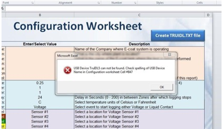
Make sure that the Device Name shown on the Configuration Worksheet Cell #B47 matches up with the USB name of your module. See next issue for more information.
Visual Basic Error Run-Time ‘52’, or ‘71’
When you press the blue button to create the TRUIDL.TXT file, Visual Basic is called upon to run some macros. Sometimes the macros are stopped and you see an error message like below:
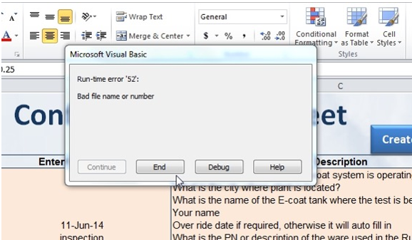
Run-Time Error ‘52’ is ‘Bad File name or Number’ and ‘71’ is ‘Drive Not Ready’, Some causes of these errors are below.
Error #52 can be caused if the TruIDL module memory limit is exceeded. This error typically occurs with firmware code “2I” or “3I”.
Error #71 can be caused if the TruIDL module is not connected to the PC. Verify USB cable is connected firmly. If problem persists, try another USB cable.
Error #71 can be caused if the TruIDL module internal memory/drive becomes corrupted. If module has firmware code “2I”, “3I”, '5A', '6A', or newer, see 'Corrupted Memory Restore' section.
Make sure the USB Device Name and the Module name are the same and the Module is connected to the PC. If using laptop connected to dock, attempt removing laptop from dock as sometimes this can cause interference from other devices.
Try a different USB cable and see if this provides any relief. USB Device Name of Module has been changed The default Device Name for the TruIDL Voltage Logger is ‘TRUIDL’. It is possible to change the name using Windows Explorer by selecting the USB device after it has been attached in the Navigation pane and using the right click on Properties. You will see a screen like below:
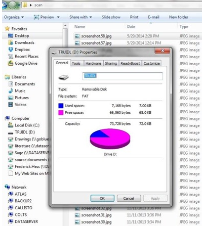
If you have two TruIDL Modules then you may want to rename them to ‘TRUIDL1’ & ‘TRUIDL2’, especially if you need to have them both attached to a PC at the same time and you want to keep them separated. The image above you can see the Device Name is ‘TRUIDL’. You may have to change the Device Name back to ‘TRUIDL’ if needed.
Putting a TC5 Configuration file on a TC10 Module
This may not happen to many of you, but if you have a TC5 and a TC10 be careful to upload the correct configuration file. In the event the incorrect configuration file is loaded, you may see a double flash from the Blue LED (i.e. problem with the configuration file) as soon as the unit has tilted.
PC asks if you want to format the TruIDL
In some cases, if the memory of the TruIDL is changed or altered in some unusual way the PC will not be able to detect the file structure and ask you if you want to format the device. If this happens, answer ‘no’ and try the items above. If the above actions do not work, then the memory of the TruIDL has been corrupted and its firmware needs to be re-flashed at UFS. Contact UFS for a Return Authorization Number and ship the module (and other items as instructed by UFS) back to UFS. If module has firmware code “2I”, “3I”, "5A", "6A" or newer, see Corputed Memory Restore below.
Only Red LED On when USB cable is attached
When the USB cable is attached to a PC the Red and Green LEDs should be On. The Amber LED will have a slow blink if the voltage is less than the Low Voltage Level. The Blue LED will be On too, if there is a fresh configuration file loaded. If only the Red LED is On, then this indicates the unit could of been dropped and the battery connector to come loose, or a battery wire has broken off. Turn to the section on Battery Care. If you are using a TruIDL Classic Logger with firmware code 5A (TC5) or 6A (TC10) then there is a known bug that does not allow the unit to wake up (the unit when to sleep at the exact same time a battery check was being performed). You will need to perform a reset. See Service Reference 990409 or Appendix L of this manual.
TruIDL Module does not wake up
If the Module does not wake up when it’s tilted, then the battery may be exhausted and it needs to be recharged. If the Red LED is on when the USB cable is attached, but the Green LED is not On, then the battery is not connected properly. If this still does not correct the matter, then maybe the tilt switch has malfunctioned. Contact UFS for a Return Authorization Number and ship the module (and other items as instructed by UFS) back to UFS. If you are using a TruIDL Classic Logger with firmware code 5A (TC5) or 6A (TC10) then there is a known bug that does not allow the unit to wake up (the unit when to sleep at the exact same time a battery check was being performed). You will need to perform a reset. See Service Reference 990409 or Appendix L of this manual.
Low Battery Voltage
A fast flash of Green/Blue/Amber LEDs happens when the USB cable is connected. This is usually a result of a very low battery condition while connected with the USB cable. If this happens, disconnect the USB cable, count to 10 and then reconnect the USB cable to allow the Module to fully re-charge the battery.
Painted/coated Voltage Sensor tip
Un-expected low voltage readings. Make sure the voltage sensor tips (i.e. brass rod) are clean of paint and also the ground clamp is clean and securely attached to the ware. In the photo below, the probe tip (which is made from shiny brass) is grey because it was covered in E-coat paint due to a short in the cable or it was able to touch the ware somehow. Use some isopropyl alcohol and the small nylon bristle brush to remove the E-coat paint solids.
If the sensor wire insulation is cut or nicked, the brass sensor tip can become painted. You will notice it by looking at the chart below. Notice how both the Orange and Grey lines appear to start normally. However, at a point, they both deviate and begin to drop. The solution is to find the damage to the insulation and re-insulate the damaged portion of the wire.
Loss of Ground connection
If all the results are zero, there may be a lack of ground. Was the Module placed on a flat steel portion of the body? Was the auxiliary ground clamp cleaned from the prior run? Was the ground clamp attached to a portion of the ware? Was it still connected to the ware after the run was over?
Broken/lost Voltage Sensor
In the event a voltage sensor has broken off, the harness may still be used. The damaged lead can be ignored. A spare sensor was included as part of the original shipment. If there was a lot of wire lost along with the sensor, the first step is to add enough wire to replace the lost amount. The spare wire is going to be black as is the heat shrink wrap. Look at the original part of the wire to identify its color. Follow the instructions that came in the spare parts kits to complete the repair.
Cut/damaged Voltage Sensor harness wire
A wire lead may have been scraped or cut. Repair parts were included in the original shipment. Make the repair with a piece of shrink wrap. Refer to the Making Repairs section for help.
Type Mismatch
If after you click the ‘Load Run Data’ button and you get an error window that says a macro has encountered a ‘Type Mismatch,’ then the run data downloaded from the TruIDL Logger has become corrupted. In this case, close the DashBoard and start over with a fresh DashBoard. Try clicking on the ‘Load Run Data’ button again. If there are still problems, contact UFS and be prepared to send both your Excel file and the TRUIDL.TXT file via email so your files can be examined.
No TRUIDL.TXT is created
If a new TRUIDL.TXT file is not created when you check the blue button on the upper right of the “Configuration” tab, make sure the Module is connected via a USB Mini Cable. From the Excel file on the ‘Configuration’ tab, make sure the cursor is not still selected in a field of the B column. If it is, then move the cursor to cell D6 – now click the blue button. The screen should flash momentarily.
Unable to copy & paste the TRUIDL.TXT file to the Module
With Rev 2 of the TruIDL DashBoard it’s no longer needed to copy and paste the TRUIDL.TXT file back and forth from the PC to the Module and then from the Module back to the PC. If you are still using the pre Rev 2 DashBoard and you are unable to copy and paste the TRUIDL.TXT file to the Module, then the unit’s memory has been corrupted and the unit has to the returned for service. Contact UFS for a Return Authorization Number and ship the module (and other items as instructed by UFS) back to UFS. If module has firmware code “2I”, “3I”, "5A", "6A". or newer then see Corupted Memory Restore below..
No TRUIDL.TXT or BAT_X_XX.VLT files are seen
If you plug the USB cable into the PC and then you select the TruIDL to view its files and there are none to be seen (as seen in the screen print below). The one known cause of this that Windows Explorer was used to format the TruIDL when it was previously attached via its USB cable. The unit may still wake up and appear to be normal. However, it cannot be Armed and it will not start logging. If this is the case, when Windows Explorer formatted the TruIDL memory it over wrote some of program memory space and thus it has become corrupted. Contact UFS for a Return Authorization Number and ship the module (and other items as instructed by UFS) back to UFS.
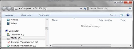
Under Liquid Sense Mode – Module starts to Log when Armed
If you have a Voltage Harness with the optional Liquid Sense sensor, you have to enable the Liquid Sense on the Configuration worksheet. You must change the Log Trigger to ‘Liquid’ (it defaults to ‘Voltage’) and when the Liquid Sense sensor is submerged the Module will begin to start logging. If you select ‘Liquid’ and when you Arm the Module it starts logging data right away (i.e. Blue LED is flashing every 4 seconds) – check the following items BEFORE you Arm the Module -WARNING WHEN NOT USING THE LIQUID SENSOR SECURE IT TO ABOVE LIQUID LEVEL OR SECURE MAGNET TO A GROUND!!!
1) The Harness (with the optional Liquid Sense sensor) must attached to the module.
2) The Liquid Sense sensor must be placed on the car body so the magnet is firmly secured to the car body.
3) The Auxiliary Ground clamp must be attached to the car body.
Corrupted Memory Restore – Firmware Code 2I, 3I, 5A, or 6A or newer ONLY
If the TruIDL module memory becomes corrupted and no other attempts to restore operation have been successful, contact UFS to verify firmware code version and then perform the following steps: Connect TruIDL module to PC using USB cable. Using Windows Explorer,
1. Right click on TruIDL drive and select Format. Use default settings below to select or enter as needed:
Capacity – 73.5 KB
File System – FAT
Allocation Unit Size – 512 bytes
Volume Label – TruIDL
Check Quick Format
Click Start.
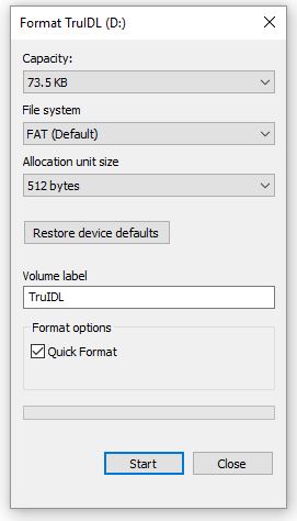
You will see a warning screen asking you if its ok to earese all data - verify its the correct drive that is selected and click OK.
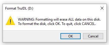
2. You mag get a warning that Windows can not complete the format or it may format as complete.
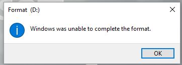
In etiher case click OK. Close Format window. Blue LED will be blinking twice (this is normal and will not happen the next time the unit is used).
3. Disconnect USB cable. The Green and Blue LEDs will be on. Verify that Amber LED is now blinking 5 times (again this is normal).
4. Reconnect USB cable and open Windows Explorer to view files.
5. Verify that TRUIDL.TXT file Date Modified is June 30, 2008 (this date is normal) .
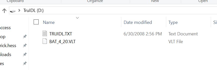
If date matches, memory restore has been successful. At this point you can use the unit again.
Sensor is not recording voltage data
If a particular sensor is not recording, then it can be something like:
1. Sensor brass tip was touching the ware and so all the values are zero and it makes it look like there is no data, it’s just really hard to see since it on the X axis along with Time.
2. Maybe the sensor wire is broken, or a solder joint has failed, or the male pin in the circular connector has been broken off.
The following items can result in damage to the Module:
WARNING WHEN NOT USING THE LIQUID SENSOR SECURE IT TO ABOVE LIQUID LEVEL OR SECURE MAGNET TO A GROUND!!!
Not Having a Secure & Persistent Ground Connection
If there is no ground connection between the Module/Harness & ware - then high voltage can enter the electronics through one of the unattached ground connections (i.e. 20 mm (3/4”) diameter magnets on the back of the module or the Auxiliary Ground Clamp). When this happens the printed circuit board is damaged and the unit has to be repaired. So always have the magnets on the back of the module attached to the ware or the ware hanger (i.e. cathode) and have the Auxiliary Ground Clamp on the ware.
Do not use metal tools to open the Clear top of Round Housings
Metal tools can damage the plastic housing. Use rubber gloves to get a good grip on the lid. If this does not work, then try a strap wrench with a rubber belt that will not mar the plastic surface.
Do not Cross Threads of Clear Top
To start screwing the Clear Top back on, place it on the Blue Bottom and turn to the left (as if you are un-screwing it slowly). Use a slight downward pressure until you hear a click. The click means the starter threads of the Top and Bottom are aligned. Now you can begin to slowly screw the Top lid by turning to the right. Do not attempt to overtighten too much. Also, make sure the O-ring is in place and it has been lubricated with 100% petroleum jelly. It is ok if some lubricant gets in the threads as well.
WIndows Explorer used to Format TruIDL Module
Do not use Windows Explorer to format the TruIDL Logger. If you do use Windows Explorer to format the TruIDL Module when it is connected via its USB cable, then the program inside the TruIDL will become corrupted. If this happens the TruIDL module will have to be returned to UFS to re-program the module. The appropriate service fee will be charged.
Using Windows Explorer to Delete TRUIDL.TXT from the Module
If you use Windows Explorer to delete the existing TRUIDL.TXT file (when attached via its USB cable) and then copy and paste or move a new TRUIDL.TXT to the module this may result in a corruption of the module memory and its firmware needs to be re-flashed at UFS. Contact UFS for a Return Authorization Number and ship the module (and other items as instructed by UFS) back to UFS.
500V Result
If a voltage curve shows a result of 500 V, it is likely a "short" has occurred. E-coat in this situation has been allowed to penetrate further than normal. Either E-coat paint has is leaking into the in the circular connector of the voltage sensor harness, or it is getting past the green O-Ring on the Module. 500 V is the maximum voltage and this can occur if a voltage greater than 3.3 V was used to input into the electronics.
Please see the previous Section called 'Preparing to Make a Run' and scroll down to the portion called Voltage Sensor Wiring Harness - use the supplied 100% petroleum jelly to lubricate the green O-Ring. If the problem persists then contact UFS as the Voltage Sensor Wiring Harness maybe need to be repaired.
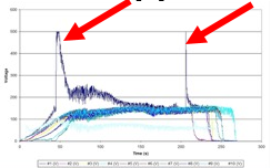
Liquid inside the Module
Is there a crack in the case? Is there another entry point for the liquid? Was the Module opened? Contact UFS Corporation for instructions.
Frosted module top
Using a solvent to clean the plastic case will result in a frosted appearance as seen below. It is possible to polish the clear top and return it to a clean state. Ask for written instructions on how to repair or return to UFS for inspection and repair.
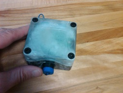
Over-exposure to Pre-treatment Chemicals
Damage to the polycarbonate case has been observed when the module was left in a hot chemical stage for 30 minutes. When the unit was then transferred to an ambient temperature rinse, stress cracks showed appeared at the corners of the case.
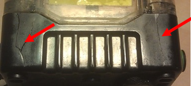
UFS recommends the module be held above the liquid level if it needs to travel through the pre-treatment stages before it gets to the E-coat tank. Use a Voltage Harness Extension cable or the Protective Jacket (PN 270300 made from PVC).
Bent Pins – Voltage Sensor Harness
Take care when pressing the circular connector of the voltage sensor harness into the mating connector on the Module. The male pins will bend if too much force is used and the connectors are not aligned.
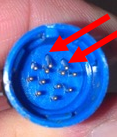
In the photo above, the top most 2 male pins are bent downward because the connectors were not aligned and too much force was used. It’s possible to use a pair of long needle nose pliers to move the bent pins.
Travel through the Oven
The TruIDL must be removed before it leaves the final post rinse and moves to the oven. The temperature in the oven is over the limit for the case and deformation of the case will result as well as damage to the Voltage Harness too. In the photo below you can see how the internal pressure bowed out the clear top. The bottom half was deformed too so that it no longer able to seal. See too that the voltage sensors were melted.
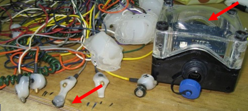
Spare Parts List
Please see the customized spare parts list for your TruIDL Logger. It can be found on the USB memory stick.
Making Repairs
Changing a Voltage Sensor
Voltage Sensor has broken off. You may continue to use the harness and just ignore the lead that was damaged. You were given a spare sensor as part of the original shipment. The spare sensor has about 3 m (10 ft), which can be trimmed as need to replace the lost amount. Hence for a sensor wire that is 3.5 m and maybe even those as long as 2.5 m long should place the splice about 30 cm from the circular connector so it is not ever in the spool. This makes it easier to wrap the excess wire on the spool, but makes it more difficult to tell the color code of the sensor. The spare wire is going to be black as well as the heat shrink wrap. You will have to look at the original part of the wire to identify its color code once the repair has been finished. Slip about 75 mm (3 inch) of the heat shrink tube over the original wire. Use a Lineman’s joint where the two wires are twisted together and soldered.
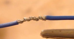
Then slip the heat shrink so it is in the middle of the joint and heat it evenly up and down and all around.
Repairing a Cut Sensor Probe Wire
A lead is scraped or cut, for example. You were given some repair parts in the original shipment. All you need in this case is a piece of the heat shrink wrap. Follow the instructions that came in the spare parts kits to complete the repair. Use a 75 mm (3 inch) length of the heat shrink tubing included in the sensor repair kit. Cut the damaged wire, slip over the heat shrink tube, make a Lineman’s repair joint (as shown above), move the heat shrink into position and heat it (as above).
Replacing USB Cap
To replace USB cap: First cut off black strap (connected to cap and unit) and insert new strap to lock into place. Apply a little of the 100% petroleum jelly to the face of the gasket to aid with sealing the connection. Add some petroleum jelly to the male threads to in order to keep paint solids from penetrating and the drying out, which can keep the cap from fully seating. (See photo below).
Returning a unit for service from outside the USA
(Make a Copy of the Form in Appendix M) Please follow the instructions on the form in Appendix M. Complete the paperwork so that U.S. Customers knows the unit is being returned for service and re-export. This will allow for proper documentation and reporting with the U.S. Authorities.
Appendix A: Amber LED Status Codes
The Amber LED will blink a certain number of times repetitively. Count the number of blinks and then look at the chart below to find the proper status. At first it may be difficult to tell the difference between one ‘long’ blink (i.e. Low Battery Voltage) and one short blink (i.e. successful data recording run). The Amber blink code will continue to be repeated until a USB cable is attached or the Module goes to sleep. If the Module goes to sleep before the USB cable is attached, the Amber code blink(s) will be re-started once it is awakened from sleep.
If you are using the firmware code “2H” or “3H” or earlier then use the Amber Flash code table below:
# Blinks	Status
1 long		Low battery
1 short		Successful run
2 short		Not used
3 short		Early Logging Termination – Full Memory
4 short		Early Logging Termination – Battery Very Low
5 short		Hardware Error (Notify UFS)
6 short		Mismatch (retry after cycling power – if still fails, Notify UFS)
7 short		WDT error (Notify UFS)
8 short		Stack error (Notify UFS)
Low Battery plus status: 1 long blink followed by a series of short blinks
If you are using the firmware code “2I”, “3I”,”5A’, “6A’ or later then use the following table:
# Blinks	Status
1 short		Successful run
2 short		Low Battery
3 short		Early Logging Termination – Full Memory
4 short		Early Logging Termination – Battery Very Low
5 short		Memory Error (Notify UFS)
6 short		Mismatch (retry after cycling power – if still fails, Notify UFS)
7 short		WDT error (Notify UFS)
8 short		Stack error (Notify UFS)
Appendix B: LED sequences
| Action | Amber | Blue | Green |
| Switch Action (tilt) | 1 flash | 1 flash | 1 flash |
| Awake/Access Mode | ** | Off | On |
| Access Mode with fresh | |||
| Configuration File | ** | On | On |
| Corrupt Configuration File | ** | 2 flash | On |
| Logging Mode, Armed | ** | 1 flash* | 1 flash* |
| Logging Mode, Live Data | ** | blinking* | OFF |
| End of Run (Access Mode) | ** | Off | On |
* every 4 seconds
** See Appendix A
The Red LED will turn On if connected to USB and the battery needs charging. The Red LED will turn Off when connected to USB and the battery is sufficiently charged (i.e. charging has stopped) or when disconnected from USB cable.
Appendix C: Specifications
| Detail | Specification |
| Full Battery Level | 4.2 Volts |
| Low Battery Level | 3.9 Volts |
| Very Low (Shut-Down) Battery Level | 3.65 Volts |
| Battery Check Frequency | 30 Seconds |
| Voltage Sensor Maximum: | 500 Volts |
| Voltage Trigger Level (start recording): | 5, 6, 7, or 8* Volts |
| InterZone Delay | 0 - 200 Seconds (24 sec*) |
| Sampling Rates (one sample every): | 0.062 Second |
| 0.125 Second | |
| 0.25 Second* | |
| 0.50 Second | |
| 1.00 Second | |
| 2.00 Seconds | |
| 4.00 Seconds | |
| Temperature Units (TU10 only) | C (Centigrade)* |
| F (Fahrenheit) | |
| Shutdown Timer: | 1-200 Minutes (1 minute*) |
* Specifies pre-configured settings at delivery
Appendix D: Data Flow Chart
Configuration and Run
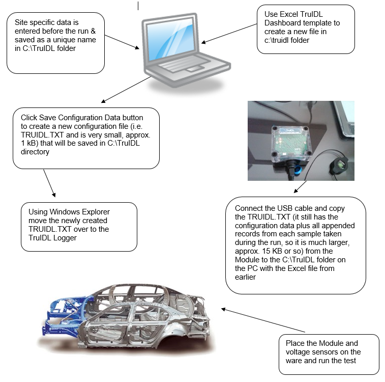
Viewing Run Data
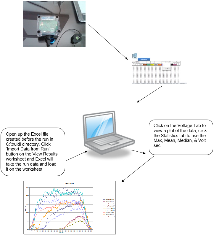
Appendix E
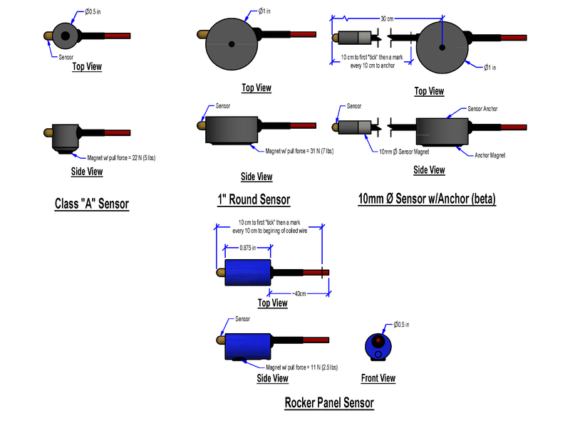
Appendix F – Typical Configuration File
This below is for the original TruIDL Logger with firmware number beginning with a 2 (TC5) or a 3 (TC10)
TC5
The file listing below is the factory default for TRUIDL.TXT for the first generation version. This file can be found on the USB memory stick as ‘TRUIDL original configuration file.TXT’. If you wanted to use it, you would have to rename the file ‘TRUIDL.TXT’ and then use Windows Explorer to upload it to the TruIDL Voltage Logger.
Note in the screen shot below shows the description after the double forward slash. In the real file the double forward slash and the descriptions are not included.
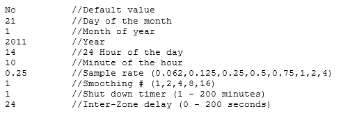
TC5
The file listing below is the factory default for TRUIDL.TXT for the TruIDL Classic Logger. This file can be found on the USB memory stick as ‘TRUIDL original configuration file.TXT’. If you wanted to use it, you would have to rename the file ‘TRUIDL.TXT’ and then use Windows Explorer to upload it to the TruIDL Voltage Logger.
Note in the screen shot below shows the description after the double forward slash. In the real file the double forward slash and the descriptions are not included.

TC10
The factory default TRUIDL.TXT file for the TC10 is the same as the TC5, except for two new parameters: temperature units & commencing of logging. Thus there are a total of 12 lines.
Note in the screen shot below shows the description after the double forward slash. In the real file the double forward slash and the descriptions are not included.

TC10 The factory default TRUIDL.TXT file for the TC10 for the TruIDL Classic Logger is the same as the TC5, except for two new parameters: temperature units & commencing of logging. Thus there are a total of 12 lines.
Note in the screen shot below shows the description after the double forward slash. In the real file the double forward slash and the descriptions are not included.
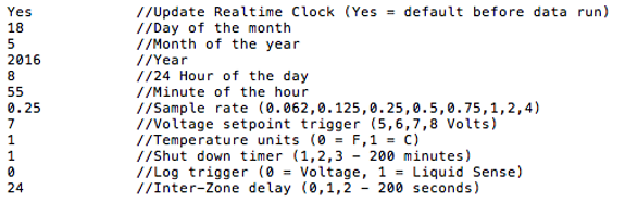
Appendix G – Typical Run File (Raw)
5 Position
Appended data begins on the 11th line and is as follows:
- Date of Run
- Time of Run
- Battery voltage
- Number of records appended
- Log entry (same as Amber Flash Code in Appendix A
- First appended file showing white, brown, green, yellow, & gray sensors
Note: The voltage values in this form do not include the decimal point. For example, the first appended record shows ‘white’ with a voltage of ‘2473’. After the decimal point is added the real voltage value is 247.3 V.
TU5
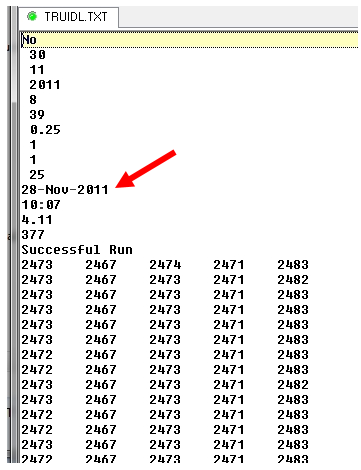
TC5
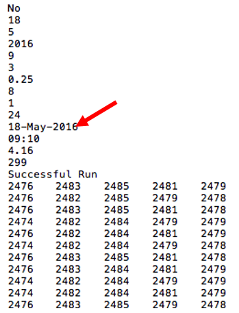
TU10
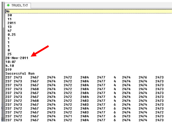
TC10
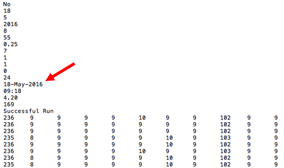
Appendix H – Field Calibration Procedure
UFS has a service to perform a periodic inspection and re-calibration for a set fee (inquire to get a quote before you send the unit in for this service). If you do not have time to send the Module and Harness back to UFS, it is possible to perform the calibration yourself if you have a 250 V class rectifier.
Safety
You must abide by the safety protocol set forth for your plant since the voltage to be used in the calibration is lethal.
Set-up
Make sure the Module and the Harness are in good condition and not damaged before you proceed.
Developer Menu
Some of the Excel Tabs you will need are hidden by default. You will have to enable the Developer function in order for the Developer to show up in the main Menu selection. Click File/Options/Customize Ribbon then click on the Developer Tab on the right and side about in the middle. Then click OK at the bottom of the window. Now you will have access to some built in macros that are needed.
Unhide Calibration Worksheets
Click on Developer and on the left hand side will be a Macro button which can be clicked to show the list of available macros as shown below:
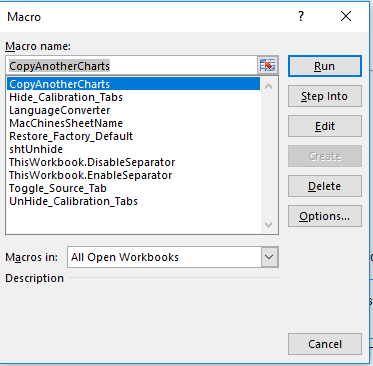
Select ‘UnHide_Calibration_Tabs’ and click Run. You should now be able to see three new Tabs: Harness Calibration Ext Cable Calibration (extension cable) Protective Jacket Calibration (white PVC protective enclosure) If you did not order a Protective Jacket, then the values in this Worksheet will not be filled in. The first two worksheets will have values since these are standard components provided with each unit. If you ordered more than one harness then there will be calibration data for each Harness that was ordered and is tracked by a separate SN on the Harness (and Ext Cable & Protective Jacket).
See Un-calibrated results
The first step is to move the ‘Calibration Factor’ back to ‘1’. This is how the calibration portion appears on the Data worksheet before the factory calibration is performed. For a TU5 there is no Temperature and only Sensors #1 thru #5. In your case the Actual column is already filled in as shown below.
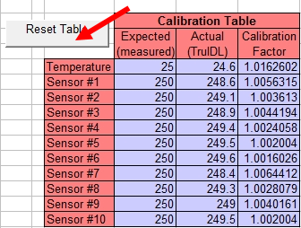
So what needs to be is to reset the chart back to a neutral position. You can click the gray ‘Reset Table’ button. After clicking the button, you will see the chart below.
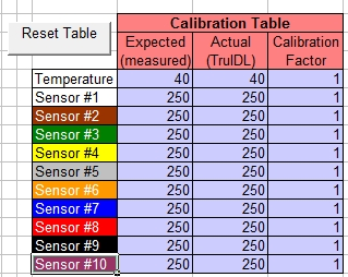
Prepare for the Calibration test
Use a calibrated thermometer (TU10 only) and establish the ambient temperature. Place cardboard box over Module to improve temperature repeatability. Take care not to breathe on the Module or place it under an air duct as it’s quite sensitive to temperature changes.
Set up the DC rectifier and use a calibrated voltmeter to measure output of the DC rectifier. Secondly use the AC V (RMS) selection on the voltmeter to sesneo how much AC Ripple is coming out of the Power Supply. Ideally it should be less than 1%, but under 5% is considered acceptable in most situations.
Create a configuration file for the run using the following parameter:
0.25 sec Sample rate or faster
0 second InterZone Delay
Voltage trigger (not liquid sense)
Voltage start of logging
Run the test for at least 60 seconds and view the results as shown below. For the first 55 seconds or so all the curves are about 250 V. When the test voltage was removed the curves went to zero during the InterZone delay period (during which the logger keeps recording) after which the logger waits 10 seconds (InterZone setting in this example) after the last sensor has dropped below 8 volts before it stops the run. So the Mean value of the Voltage for each Sensor will be influenced by the 10 seconds spent at or near zero. On the other hand, the Median value will take the sample halfway or about 33 seconds – when the test voltage was applied. You might also consider using the maximum value and making decision as to which one to use or maybe a point in between. In this case there is only 0.2 V or so difference between the Median and the Maximum
An alternate method is to look at the data on the Run Data Tab and eliminate the beginning 5 to 10 seconds (where the power supply starts p) and the ending 5 or 10 seconds.Then compute an average for each channel and insert this average value into the ‘Recorded Value’ column of the Calibration worksheets.
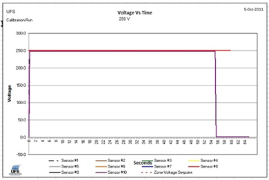
Statistics
After you download the data run. Look at the ‘Statistics’ worksheet. The Median or Maximum value will provide the best results for the purpose of calibration. Since this is a calibration run the data in the lower table is the factory default values. While in the upper table are the Max, Mean, Median, and Volts x Seconds (N/A for Temperature). For example, for the Temperature: Max was 21.0 (i.e. units are C) and the Median was 20.9. For Sensor #5: Max was 249.2 (i.e. units are V) and Median was 249. Print out a copy of this page because you should save a hard copy of this in your permanent records, and you will need the values when entering the calibration data shortly.

Here is the Actual data entered from using the Median Values from the calibration data run (above). Note the Expected value for temperature was adjusted from the default value of 25 C to the room temperature where the test was conducted, which was 23 C. On the Statistics Page you want to enter the Date in cell M25 and your initials in M26.
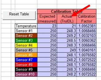
Rerun the Calibration test
Running the test a second time will show you the calibration corrects the results, usually to about +/- 0.5 V. In the example below, a test was done at 250.0 V. The Median for each of the 10 Voltage Sensors was 250 V, which is inside the goal of +/- 0.5 volts after a calibration run. The temperature was corrected up to 22.9 C from its original value of about 21 C.
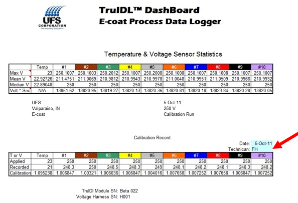
Change the DashBoard Template
You need to create a new DashBoard to use the new calibration. The original DashBoard was created with a factory calibration performed. You can do this by starting with a fresh copy of the existing TruIDL DashBoard and the revising the calibration values on Data worksheet. Then do a Save As and select .xlt (2003) or .xltm (2007 or 2010). Make sure and fill in the date of the calibration and your initials.
Appendix I - Keys to Success with Wire Spool
Take special care to avoid damage to the insulation of the wire for each of the sensors. Wind up the excess wire on the spool and then use two thumbs to press down on the wire into its capture point to keep from getting tangled.
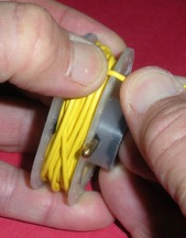
Do not attempt to pull the wire lead connected to the voltage sensor body from the ware, metal desk top, or metal lab bench. You may break the wire, or cause the magnet to break free and cause injury. Always grasp the voltage sensor itself and lift it first. You can then use the other hand to gather the excess wire.
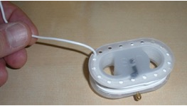
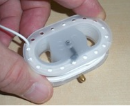
Appendix J – Aluminum Adapter Accessory
The voltage sensors use a magnet to attach to the steel substrate of the ware. When the ware is aluminum, this strategy will not work. If you are using the Class A sensor type, then you can use the adapter shown below.


Insure the Brass Tip will not be able to rotate so much it is no longer directly above the flat surface of the ware.
| UFS PN | Color Code | Ware thickness (mm) | Ware Thickness (in) |
| 073024 | Red | 1.016 – 1.524 | 0.040 – 0.060 |
| 073025 | Navy Blue | 1.524 – 2.286 | 0.060 – 0.090 |
| 073026 | Orange | 2.286 – 3.429 | 0.090 – 0.135 |
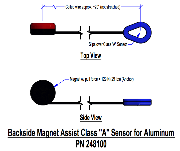
Appendix K – TSA & Customs Information Sheet
Media:994419 TruIDL Data Logger - For Customs & TSA Personnel.pdf
Appendix L How to Reset
Service Reference - TruIDL Logger - How to Reset
Appendix M - Export Goods Back to US for Inspection/Repair
TruIDL Return Procedures Shipping instructions for returning goods from outside the US:
1. Please make sure that UFS Corporation has issued you a Return Authorization Number (RAN). This is done by contacting service@ufsc.com, calling +1 219-464-2027, or contacting your UFS Corporation representative.
2. The parts being returned must match original order.
3. The parts must be returned in adequate condition in proper packaging and shipping material. Failure to do so will result in product being returned to sender.
4. Please mark the outside of the package with the following statement. “Return of UFS Corporation Manufactured Goods for Repair”.
5. Check with your country’s Customs Authority and register the goods before sending it to the United States for repair. Include with the shipment any documentation or other information needed to return the repaired goods to you.
6. Prepare a commercial invoice, as per the attached sample, so that the goods will not be assessed a duty when imported into the USA.
7. Fill out the following information, and include it with the returned goods.
ADD SHEET/FORM
BULLETIN 994417