TruIDL Quick Start
Contents
Product Support and Customer Service
For Further support visit our Contact Page
What's Included
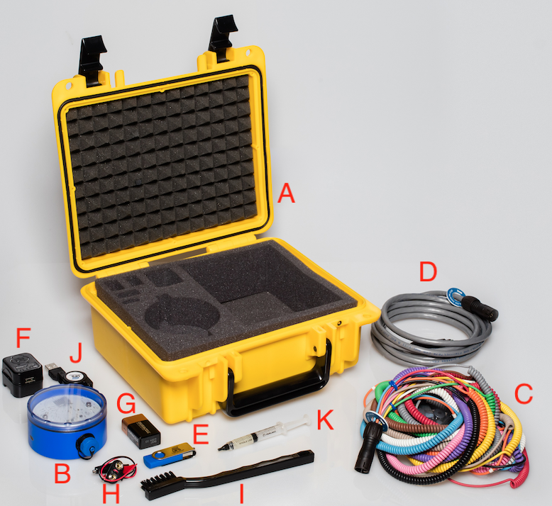
- A - Carrying Case with foam cut-outs
- B - TruIDL Classic Logger
- C - Voltage Sensor Harness
- D - Extension Cable
- E - USB stick that includes manual, spare parts list and Excel template
- F - Universal Wall Charger
- G - 9 V Battery
- H - Alligator Clips
- I - Small Plastic Hand Brush to clean wire parts
- J - Mini USB Retract Cable
- K -100% Petroleum Jelly w/syringe
Included buy not shown - Calibration Report, Blind Plug Adaptor, Aluminum Adapters for Class A Sensor, Voltage Sensor Wire Repair Kit, Quick Start card and Plastic Tie Wraps.
LED Explanation Key
| Color | Explination |
| RED | Battery Charging |
| GREEN | Unit is Awake |
| Blue | Configuration file is uploaded |
| GREEN and BLUE FLASHING | Unit is Armed |
| BLUE FLASHING | Unit is recording data |
| AMBER | Amber LED Status Codes |
Amber LED Status Codes
Amber LED Status Codes The Amber LED will blink a certain number of times repetitively. Count the number of blinks and then look at the chart below to find the proper status. At first it may be difficult to tell the difference between one ‘long’ blink (i.e. Low Battery Voltage) and one short blink (i.e. successful data recording run).
| # Blinks | Status |
| 1 short | Successful run |
| 2 short | Low Battery |
| 3 short | Early Logging Termination (Full Memory) |
| 4 short | Early Logging Termination (Battery Very Low) |
| 4 short | Memory Error (Notify UFS) |
| 6 short | Mismatch (retry after cycling power. If still fails, Notify UFS) |
| 7 short | WDT error (Notify UFS) |
| 9 short | Stack error (Notify UFS) |
Charging the battery
Unless the unit was used in the past 5 days, the battery voltage may be too low to wake up. Unscrew the blue cap covering the Mini USB connector. Take the Mini USB cable and connect it to the unit and then your PC. Battery charging time can be reduced by using a USB AC Wall Charger. The Red & Green LEDs should be On. The Amber LED will have a slow flash (if battery level is low) and the Blue LED may be On or Off. After 90 minutes or so the Amber LED will stop blinking, which means the voltage is above the Low Level. After the battery is fully charged, the Red LED will be off and just the Green LED on (Photo 1). Note - your Blue LED may be On, which indicates it has a fresh configuration file. If you remove the USB cable from the TruIDL Logger, it will then go to sleep at the Shutdown timer value, unless there has been some activity; another USB connection; or a tilt.
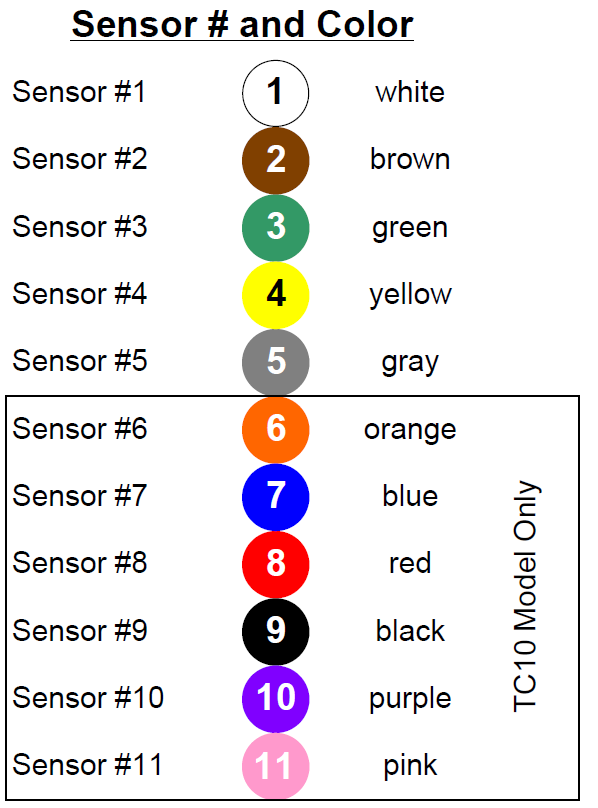
Voltage Sensor Quick Identification Colors
How to Perform a Battery Test
Upload configuration file onto the unit. Attach your Voltage Sensor Harness to the Module. Take the 9V battery, the red and black battery clips, and connect the side of the leads to the top of the battery. Observe the polarity. Next attach the black lead to the ground clamp of the Voltage Harness (tan coiled wire). Wake the unit up with one tilt (if it went to sleep). Then tilt it again to Arm it. Now the Green and Blue LEDs should flash once every 4 seconds. Place the red lead on the White sensor tip and hold for 5 seconds. Do you see just the Blue LED flashing every 4 seconds now? Move the red clip to brown, green, yellow, gray, (next 5 are for TU10 models only) orange, blue, red, black, and purple. Remove the red clip and wait for the InterZone time-out to complete. Afterwards the Green LED is On and the Amber is flashing every second or so, which means ‘Successful Run’. Download the data back to the Dashboard and look at the chart.
Keys to Success
- Charge the battery the night before with the USB wall charger.
- Clean the sensor tips, ground clamp, and magnets on bottom of module after each Run.
- Keep sensor wires untangled after each Run.
- Secure ground clip to the ware.
- Remove the TruIDL Logger & Harness before the curing ovens!
- Use extension harness to raise unit above liquid level if unit attached before pretreatment!
- Clean up only with isopropyl alcohol.
- Use a camera to document the sensor locations.
TruIDL Tips and Tricks
- Use six sensors on just one side of the car body so a line stop may not be needed. You will need to do a second data run for the other side of the body.
- Charge the unit completely the night before a run.
- Create an account in your company’s cloud to store your data, so it can be shared, retrieved, and backed up.
- If placing sensors only in the interior - do not forget to place at least one voltage sensor on the exterior (close to anode cell), so it starts logging soon after the ware enters the E-coat bath.
BULLETIN 994421