TruAmp100 Manual
Contents
Product Support and Customer Service
For Further support visit our Contact Page
What is Included
The TruAmp100 Logger is a battery powered amp-hour meter that shows the remaining life of the ion-exchange membrane of the anode cell used in E-coat paint application.
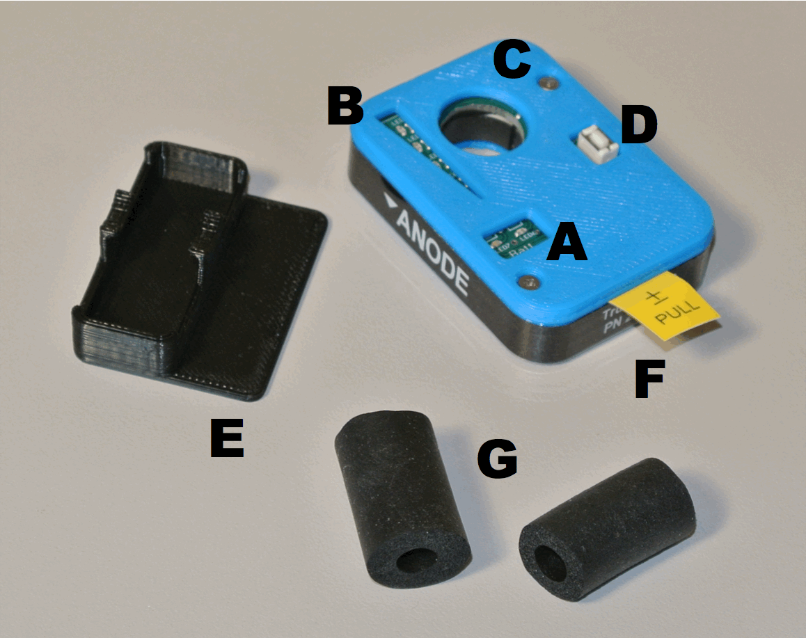
A: Battery Status LEDs. B: Ion-Exchange Membrane Remaining Life LEDs. C: 12.5 mm (1/2”) Passageway for Anode Cell Cable Lead. D: Button to press to see remaining Ion-Exchange Membrane Life. E: Paint Splash/Drip Guard (loose). F: Battery Pull Tab. G. Wire Centering Rings (loose)
Installation and Startup
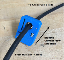
The button side of the device must be pointing towards the Anode Bus Bar. Take the Anode Cell cable lead and pass it through the opening.
2 Wire Centering Rings are provided Use the larger OD piece for AWG 12 – 6 THHN, or Use the smaller OD piece for AWG 8 – 6 Welding cable. For larger AWG 4 – 2 cables, do not use the Wire Centering Rings. Install the Wire Centering Ring over wire at location where the Logger is meant to be located.
If necessary – remove the lug before hand and reattach a new one afterwards. Move Logger so foam ring is inside “C.”
If the Wire Centering Ring is not required because of the large wire size, you still may be able to use the one or both to act as a stop to keep the Logger from sliding down the wire one direction or the other.
Pull the Battery Start tab (Item F)
Install the Splash Guard (Item E) over the top. Note – this has a loose fit design so it can be removed if necessary and not break the tabs.
The Unit is now recording data every 1/8 of a second.
The unit has been pre-programmed based upon the amount of ion-exchange surface area in the anode cell to which it is to be attached. When the battery start tape is pulled, the unit will start up.
The ion-exchange membrane surface area is pre-programmed as a metric unit value of m^2. The value could be something like 0.235 m^2. Once you pull the battery tab, you will see the pre-programmed value of the ion-exchange membrane surface area flashed on the Ion-Exchange Remaining Life LEDs. The following flash codes will appear:
Green ‘Ones’ value ‘0’ Slight delay, LED is off Green ‘Tenths’ value ‘2’ Flash 2 times Amber ‘Hundredths’ Value ‘3’ Flash 3 times. Amber ‘Thousandths’ Value ‘5’ Flash 5 times Red – not used
The surface area flash pattern will be repeated 2 times.
If you do not see the proper initial LED sequence, please contact UFS Corporation for technical support.
Press the button no more than once every 30 days to see how much life is remaining of the ion-exchange membrane (not the metal anode).
This device is meant to be installed on new Membrane Shells, C Cells or Box Anode Cells where the ion-exchange membrane is new.
There are 5 LEDs in a vertical pattern as shown below. When new, all 5 LEDs will be On when the button is pressed and released. As the Life Remaining is reduced, the top most LEDs will no longer illuminate.
Green 80 to 100% remaining Green 60 to 79% remaining Amber 40 to 59% remaining Amber 20 to 39% remaining Red 10 to 19% remaining Red, fast flash 0 to 9% remaining
Red, slow flash No Remaining Design Life left. Red LED will continue slow flash pattern to indicate cell is completely used.
As long as the Battery voltage is more than 2.7 V the Green Battery LED will be On. Once the voltage falls below 2.7 V, the Red Battery LED will flash and the battery needs to be replaced. The accuracy of the device is compromised at low battery voltage levels or it may quit entirely. The data will be kept even though the battery has gone dead. Change the battery as soon as possible so not much data is lost during the battery outage.
Note: The TruAmp Logger is not meant to be re-used since it cannot be reset in the field. Do not re-use an old TruAmp Logger on a new anode cell or Membrane Shell.
Trouble-Shooting
Red Battery LED is Flashing
Unit must be removed from the cable connecting it to the anode cell. Follow rules on turning off the DC power rectifier, entering the E-coat tank before any task is attempted.
Only use a CR2032 coin replacement battery. To remove the cover of the unit you must first remove the Splash Guard and set aside. Then use a #0 Phillips screwdriver to remove the two screws and set aside. Remove the printed circuit board with your pinky finger placed into the toroid. Turn the printed circuit board over to view the battery. Pry the old battery out of the holder and place the new one in its place. As you press the new battery into place –check the other side of the unit to see the LEDs flash their power-on startup sequence.
Dispose of the battery in the appropriate manner for your locality. Do not put into the trash.
Both Battery LEDs and all the Ion-Exchange Membrane LEDs are On. Following this the Green battery LED will remain On while the pre-programmed membrane surface area LED flash pattern occurs. Once the pattern is complete, all LEDs should be Off. Then you can press the button and only the LEDs representing how much life is remaining will be showing on the vertical LEDs.
Note: If you reinstall the battery to look at the LEDs a second time, hold the switch down for 15 seconds BEFORE the battery is re-inserted into the holder - this will allow the capacitor to discharge and allow a normal re-start after a battery change.
Place the front cover on and re-attach with the 2 screws. Then place the Splash Guard back on the top.
Re-install the unit only on the anode cell from which it was removed.
BULLETIN 994418