Interpretation of Ion-exchange Membrane Surface Resistance Testing
Product Support and Customer Service
For Further support visit our Contact Page
General
When an Anode Cell is new, the electrical resistance due to the ion-exchange membrane is very low, in the range of 25 to 50 Ohm*cm^2. It is so low that it is almost invisible to the flow of electrical current, which performs the work as the Electro-coat paint is deposited on the ware.
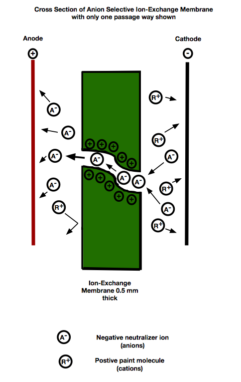
Ion-Exchange Membrane works on the principle of “attraction of opposites”. In cathodic type electro-coat paint, the neutralizer is an anion. The anion selective membrane uses cations inside the structure of the membrane to allow the passage of anions while excluding any cations (i.e. paint molecules). The typical ion-exchange membrane is only ½ mm (~0.020 inches thick) and there are many passageways in which anions travel. With operation, age, contamination, and wear the membrane loses these passage ways. The passage ways that remain open can only handle so much current. The operator of the Electro-coat system will have to raise the rectifier voltage to compensate for the natural aging process of the membrane.
Older ion-change membrane that has reached the end of its useful life will have a Surface Resistance in the range of 20,000 - 25,000 Ohm*cm^2. In addition to the passage ways closing off, there can be contamination on the inside face of the membrane as well a fouling layer on the exterior of the membrane.
If electro-coat paint gets inside the Anode Cell it will act as a contaminant and will form a resistive layer. Since the paint is a cation species it is not allowed to go through the membrane. At the same time the anode has a high positive voltage which repels the paint molecule. The paint molecules wind up smashed against the membrane. A fouling layer forms on the membrane which leads to higher levels of required voltage.
The fouling layer on the exterior of the membrane can be dried electro-coat paint, pre-treatment carry over attracted to the anode cell, or fouling attached to the external wrap around tubular anode cells. In some cases the fouling layer can be cleaned off with a UF type cleaner that is compatible with the E-coat paint.
TECTRON Anode Cells can perform service in electro-coat paint systems for many years. 7 or 8 service years are not un-heard of. The typical service life for the 1-1/2 inch Size TECTRON Cell is 20,000 hours as long as the anode current density is less than 50 amps/m^2 (5 amps/SF).
The membrane sample sent to UFS for testing was tested in a 1 liter glass beaker. A membrane coupon was cut from the provided sample and placed into an apparatus that served as an anode cell. An anode and cathode were placed at about 5 cm (4-1/2”) and the electro-coat paint and anolyte were represented by a mixture of DI water and latic acid to a conductivity of about 1400 uS/cm.
A 15 V rectifier was used to pass current, which was measured. The resistance of the membrane was estimated using the current and the applied voltage. The background resistance of the apparatus was subtracted so we arrived at the resistance due only to the membrane. The results were plotted on the attached chart.
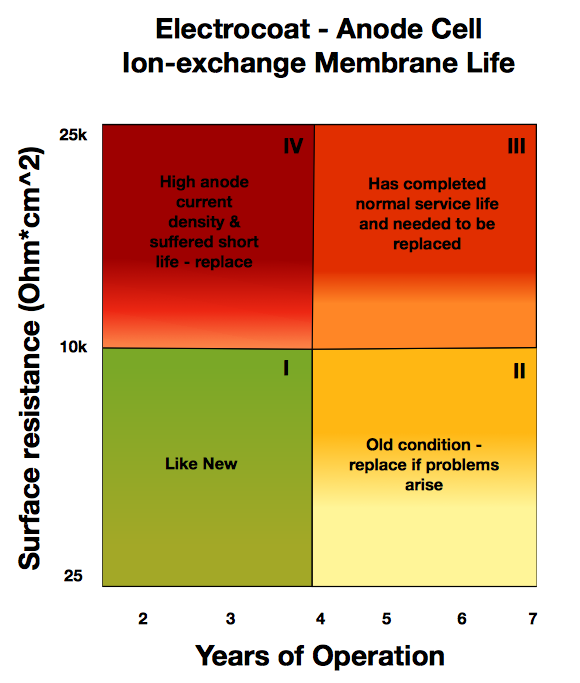
The horizontal axis shows the # of Years the Membrane has been in service. The vertical axis is the Surface Resistance of the membrane expressed in Ohm*cm^2.
The green quadrant represents membrane that is close to New condition since it is less than 3 years old and the Surface Resistance has not yet passed the half way mark.
The yellow quadrant represents Old condition but the Surface Resistance has not yet reached the ½ mark. In some cases the Cells can still be used. If there is any trouble with the formation of the electro-coat film or the pH of the bath is persistently low, it is time to change the membrane.
The red quadrant portrays young cells that have been over-worked and need to be changed ASAP. If replacement cells have been mixed in amongst old Cells, the new replacement cells are carrying too much electrical load. The older Cells have more resistance so do not share the load equally with the new Cells.
The orange quadrant depicts the old cell condition plus high Surface Resistance. These Cells have served their normal service life and its time to replace. The closer to the 25k Ohm*cm^2 point the faster the cells should be changed. It is a dangerous condition to operate anode cells with a membrane Surface resistance approaching 25k Ohm*cm^2.
BULLETIN 991211